
Inductive vs Capacitive Proximity Sensor: Selection by Target Material

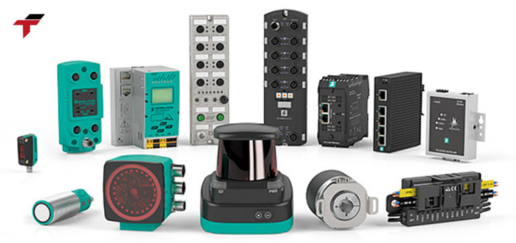
An inductive proximity sensor detects metal only; a capacitive proximity sensor detects both metal and non-metal targets, including plastic, liquid, wood, and glass. That single difference in target material capability is what decides most inductive-vs-capacitive selection questions on a Malaysian factory floor, long before sensing distance, output type, or price enter the conversation. Both are non-contact detection devices built around an oscillator circuit, but the field each one generates interacts with a different property of the target — a magnetic field reacting to metal in the inductive sensor, and an electric field reacting to any material with mass or dielectric properties in the capacitive sensor.
This guide compares how each sensor detects its target, lays out the sensing-distance and form-factor differences a system integrator checks against a datasheet, and walks through the target-material decision framework directly — metal-only detection tasks favour an inductive sensor; non-metal or mixed-material detection tasks call for a capacitive sensor. It closes with where each sensor type shows up across Malaysian production lines and the questions procurement teams raise most often when specifying one over the other.
What Separates an Inductive Sensor From a Capacitive Sensor
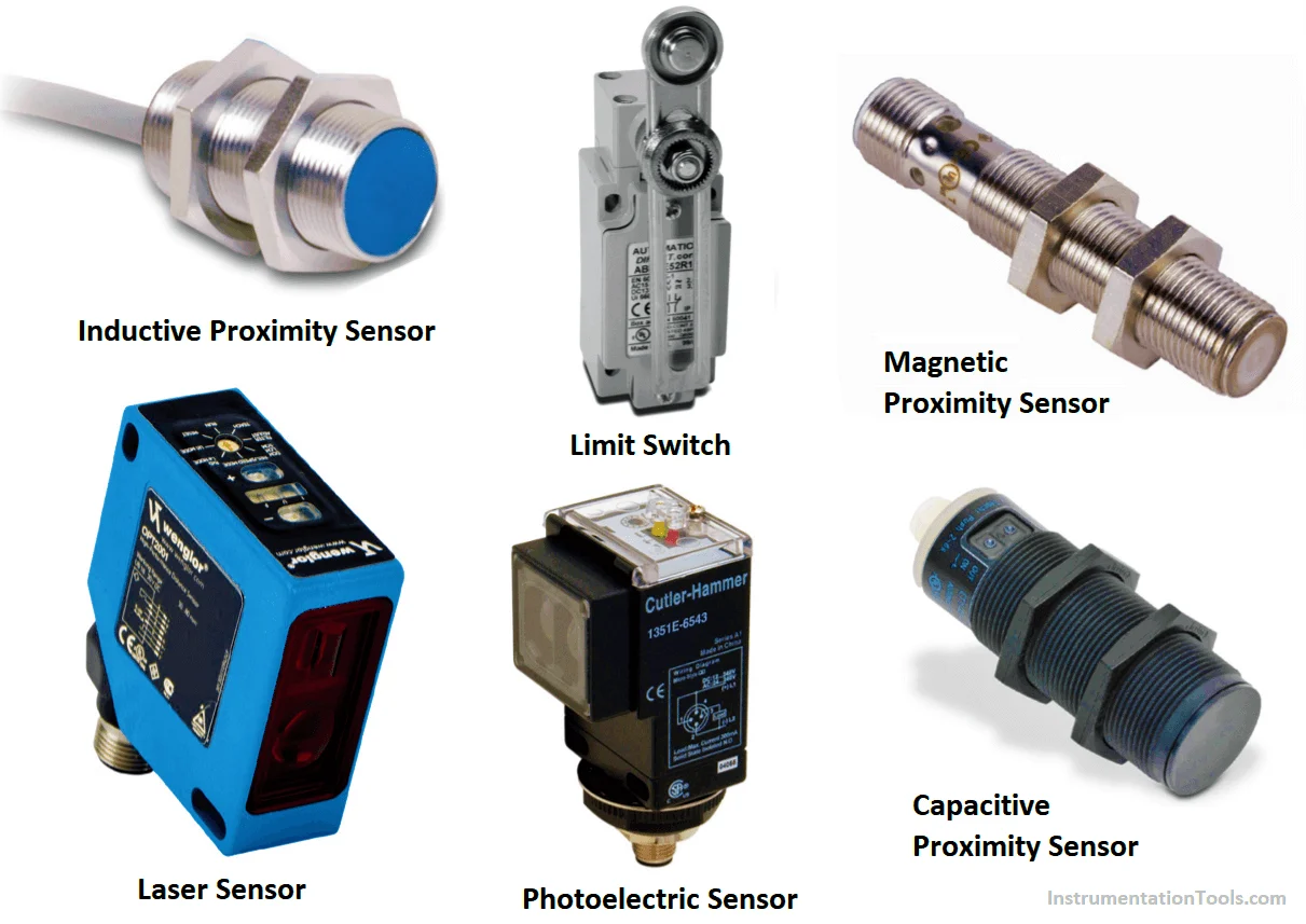
An inductive proximity sensor and a capacitive proximity sensor share the same basic architecture — an oscillator circuit generating a field in front of the sensor face, and a threshold circuit that switches an output when the field is disturbed by a target entering the detection zone. What differs is the physics each one reacts to. The inductive sensor’s coil produces an electromagnetic field that only conductive metal disturbs, which is why an inductive sensor is fundamentally a metal detector. The capacitive sensor’s plate pair produces an electric field sensitive to the dielectric constant of whatever enters it, which is why a capacitive sensor reacts to metal, plastic, liquid, powder, and glass alike.
That target-material distinction carries directly into sensing distance: inductive sensors typically detect from 1mm to 50mm depending on target size and sensor barrel diameter, while capacitive sensors typically detect from 3mm to 20mm — a narrower window, because a capacitive field has to distinguish target material from ambient air and humidity rather than simply detecting conductive mass. With the core distinction established, the mechanism behind each sensor is worth walking through individually before comparing them side by side.
What Separates an Inductive Sensor From a Capacitive Sensor
How an Inductive Proximity Sensor Detects Metal
An inductive proximity sensor works by continuously running an oscillator circuit — an inductive coil paired with a capacitor — that produces a self-sustaining electromagnetic field at the sensor’s active surface (the face behind which the coil sits). When a metal target enters that field, the field induces small circulating currents in the metal called eddy currents. Generating those eddy currents draws energy out of the oscillator, so the oscillation’s amplitude drops. Once the amplitude falls below a preset threshold, an internal Schmitt trigger circuit fires and switches the sensor’s output — confirming that a metal target is present.
This is why an inductive sensor only ever detects electrically conductive material: no eddy currents form in plastic, wood, liquid, or any other non-conductive target, so the oscillator’s amplitude never drops and the output never switches. Standard inductive sensors are tuned to detect ferrous metal (steel, iron) at their rated sensing distance; detecting non-ferrous metal like aluminium or brass at the same distance requires a specialty “Factor 1” model built to respond equally to all metal types, since non-ferrous metals otherwise reduce the effective sensing distance compared to steel.
That metal-only limitation is precisely what a capacitive proximity sensor removes, at the cost of a different set of trade-offs covered next.
How a Capacitive Proximity Sensor Detects Non-Metal and Metal Targets
A capacitive proximity sensor replaces the inductive coil with a capacitor plate arrangement at the sensor face, and the oscillator’s behaviour changes with the target’s dielectric constant rather than with conductive mass alone. As a target — metal or non-metal — approaches the plates, it changes the effective capacitance of the circuit, which shifts the oscillator’s amplitude the same way a metal target shifts an inductive sensor’s amplitude. Once that shift crosses the threshold, the output switches.
Because capacitance changes with any material that has sufficient mass or a distinct dielectric constant from air, a capacitive proximity sensor detects plastic, glass, wood, liquid, granular material, and powders in addition to metal — the property it measures is not electrical conductivity but the target’s effect on an electric field. This is also why capacitive sensors are the standard choice for liquid-level detection through a non-metallic tank wall, and why the same underlying sensing principle appears in capacitive touch sensor technology used on HMI panels and control interfaces, where a fingertip’s dielectric effect is what the sensor is built to detect. With both mechanisms established, the practical comparison is best seen side by side.
Inductive vs Capacitive Proximity Sensor — Side-by-Side
| Attribute | Inductive Proximity Sensor | Capacitive Proximity Sensor |
| Target material detected | Metal only (ferrous standard; non-ferrous needs Factor 1 model) | Metal and non-metal (plastic, liquid, wood, glass, powder) |
| Detection principle | Eddy currents in a metal target, induced by an electromagnetic field | Change in capacitance, driven by a target’s dielectric constant |
| Typical sensing distance | 1-50mm (0.04-2 in) | 3-20mm (0.1-0.8 in) |
| Best suited for | Metal-part presence/position detection on a production line | Non-metal or mixed-material detection, liquid-level through a tank wall |
| Environmental sensitivity | Largely unaffected by non-metallic dust, oil film, or ambient humidity | Sensitive to humidity and buildup on the sensor face — dielectric changes can trigger false detection |
| Common form factors | M8/M12/M18/M30 cylindrical barrel, shielded and unshielded | M12/M18/M30 cylindrical barrel, generally shielded |
Both sensor families operate on a standard 10-30VDC supply range and are offered with the same NPN/PNP output logic conventions used across the broader proximity sensor family — the electrical integration side is largely identical, which keeps the target-material decision the dominant factor.
The table above compresses six comparison points into one reference; the callout below restates the two that carry the most weight before the decision framework turns them into a selection rule.
Inductive vs Capacitive Proximity Sensor — Side-by-Side
Summary So Far
An inductive proximity sensor detects metal only, using eddy currents induced by an electromagnetic field, at a typical range of 1-50mm. A capacitive proximity sensor detects both metal and non-metal targets — plastic, liquid, wood, glass, powder — by sensing a change in capacitance driven by the target’s dielectric constant, at a shorter typical range of 3-20mm. Both share the same 10-30VDC electrical integration and M8-M30 cylindrical form factors, so target material, not wiring or mounting, is what drives the choice between them. The next section turns that distinction into a selection framework, followed by form factor, output type, and application detail.
Selecting by Target Material — the Decision Framework
The selection decision starts with one question: is the target metal, and is it the only material the sensor will ever encounter in that detection zone? If the answer is yes — a metal bracket on a conveyor, a machine part in position on a jig, a metal gear tooth for counting — an inductive proximity sensor is the correct and lower-cost choice, and its narrower sensitivity to non-metallic contamination (oil, dust, non-metal debris) is an advantage rather than a limitation in that context.
If the target is non-metal, or the detection point sees a mix of materials over the sensor’s service life, a capacitive proximity sensor is the correct choice — it is the only one of the two that reacts to plastic components, liquid levels, wood pallets, or granular/powder material at all. The trade-off runs the other way in dirty or humid environments: because a capacitive sensor reacts to any material change at its face, condensation, oil film, or material buildup on the sensor itself can trigger a false detection that an inductive sensor, indifferent to non-metallic material, would ignore. A system integrator specifying a capacitive sensor for a humid or oily production environment in Malaysia — palm oil processing or rubber and glove manufacturing, for example — needs to weight that environmental sensitivity against the material-detection requirement before finalising the choice.
Once the target-material call is made, the remaining specification decisions — barrel size, shielding, and output type — apply the same way to either sensor family.
Form Factors and Output Types
Both sensor families are supplied in the same cylindrical barrel form factors — M8, M12, M18, and M30 — sized to the mounting space and required sensing distance. The designation is the barrel diameter itself: M8 (8mm / 0.31 in), M12 (12mm / 0.47 in), M18 (18mm / 0.71 in), and M30 (30mm / 1.18 in), with larger barrels generally supporting a longer sensing distance within each sensor family’s range. Within each barrel size, sensors are offered shielded (the coil or plate is recessed behind a metal housing, allowing flush mounting in a metal surface at the cost of shorter range) or unshielded (the field extends further but the sensor needs clearance from surrounding metal to avoid false triggering). Output logic follows the same DC 2-wire, NPN, or PNP conventions used across the industrial sensor family, with IO-Link increasingly offered on both inductive and capacitive models for bidirectional configuration and diagnostic data.
On wiring and control diagrams, an inductive proximity sensor symbol typically shows a labelled rectangle or circle with a coil icon and the switching output (normally open or normally closed) indicated alongside the connector pin-out — the same schematic convention system integrators reference when cross-checking a PLC input wiring diagram against a datasheet, regardless of brand. Flextech Industrial carries Autonics and Omron proximity sensors; an Omron inductive proximity sensor catalogue lists both standard and Factor 1 models across the M8-M30 barrel range described above, alongside the shielded/unshielded and output-logic variants covered here.
With mechanism, sensing distance, and form factor established, the remaining question is where each sensor type actually shows up on a Malaysian production line.
Form Factors and Output Types
Where Each Sensor Type Is Used in Malaysian Manufacturing
Inductive proximity sensors are the more commonly specified of the two across Malaysian manufacturing lines, because most position, presence, and counting detection tasks on a production line involve a metal part, tool, or fixture. Typical inductive proximity sensor applications include detecting metal component presence on assembly and packaging lines in electronics and semiconductor manufacturing (Penang), confirming machine part position on conveyor and indexing systems, and counting metal parts or fasteners on high-speed production. In semiconductor and precision electronics assembly specifically, the tight tolerances involved make an inductive sensor’s fast, contact-free switching preferable to a mechanical limit switch that would wear from repeated cycling.
Capacitive proximity sensors see targeted use wherever the material is non-metal: level detection through the wall of a non-metallic tank or hopper in food & beverage and palm oil processing, detecting plastic or paper packaging presence on a line, and — in the HMI/control panel context rather than the production line itself — capacitive touch sensor technology on operator interface panels. Rubber and glove manufacturing, an industry Flextech Industrial serves across its Malaysian customer base, uses both: inductive sensors for metal mould and fixture detection, capacitive sensors for detecting rubber compound or liquid latex level where a metal-only sensor cannot see the target at all.
Frequently Asked Questions
These frequently asked questions cover the points that come up most often once the target-material distinction above is settled — cost, common drawbacks, and how the inductive and capacitive families compare to a third proximity technology, magnetic.
How much do inductive proximity sensors cost?
Inductive proximity sensor cost varies by barrel size, sensing distance, output type, and brand, and Flextech Industrial does not publish a single fixed price list across its inductive sensor range — a specific quotation depends on the model and quantity required. Standard general-purpose models sit at the lower end of the industrial sensor price range; specialty variants (Factor 1, weld-immune, IP69K washdown, IO-Link) cost more due to the added materials and electronics. The same pricing pattern applies to capacitive proximity sensor price — specialty and larger-barrel models cost more than standard general-purpose units.
What are the disadvantages of inductive proximity sensors?
The main disadvantage of an inductive proximity sensor is that it only detects metal — it is not a general-purpose presence sensor. Its sensing distance is also shorter than photoelectric or ultrasonic alternatives, and standard models detect ferrous metal more reliably than non-ferrous metal unless a Factor 1 model is specified.
How does an inductive proximity sensor differ from a magnetic proximity sensor?
An inductive proximity sensor detects any metal target directly, using an electromagnetic field and eddy currents, without requiring anything attached to the target. A magnetic proximity sensor, by contrast, detects a magnet — it requires a magnet mounted on the moving target and reacts to that magnet’s field rather than to the target’s own material, which makes it a different detection method suited to different mounting situations even though both are grouped under the broader proximity sensor category.
How far can a capacitive proximity sensor detect?
A capacitive proximity sensor senses in the 3mm to 20mm range (about 0.1 to 0.8 inches), narrower than the 1mm to 50mm range (about 0.04 to 2 inches) typical of inductive sensors. A capacitive field distinguishes the target’s dielectric effect from ambient conditions rather than simply detecting conductive mass, which is the reason for the shorter, more tightly controlled range.
For selection guidance across Flextech Industrial’s full sensor range — including inductive, capacitive, photoelectric, and load cell types — see the Industrial Sensors Malaysia category, or the broader Proximity Sensor Guide covering all five proximity sensing technologies. For a specific application, Flextech Industrial’s technical team can advise on inductive vs capacitive selection across Selangor, Penang, and Johor.