
PLC Ladder Logic Explained: Diagrams, Rungs and Real Examples

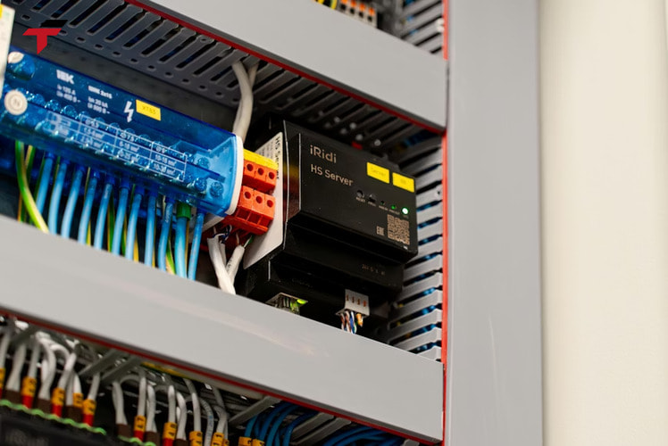
Ladder logic is the graphical programming language used to write the control program inside a Programmable Logic Controller (PLC), drawn as two vertical rails joined by horizontal rungs, each rung standing for one control rule. The layout mirrors a relay-panel wiring diagram on purpose: the International Electrotechnical Commission formalises this graphical form as Ladder Diagram (LD) under IEC 61131-3, and factories kept the relay-style drawing so electricians could read PLC logic without first learning a text-based language.
Reading ladder logic starts with the scan cycle that turns a rung into live output, continues through a symbol table cross-referenced against Siemens and Allen-Bradley naming, and closes on two full worked rungs — building a motor seal-in circuit and reading a finished overhead-door panel — for engineers programming or troubleshooting a PLC rung by rung.
What a Ladder Diagram Actually Represents
A ladder diagram is not a picture of wiring — it is the symbolic representation of the control logic that a PLC executes, drawn to resemble the relay circuits it replaced. Two vertical lines, called rails, run down each side of the page; horizontal lines called rungs connect between them, and each rung carries one self-contained piece of control logic. The naming follows the shape: two rails plus a series of rungs looks like a ladder, hence “ladder diagram.”
The resemblance to relay wiring was deliberate. Before PLCs, a control system such as a conveyor or a pump station was hardwired using physical relays: cutting and re-terminating wires was the only way to change behaviour. When PLCs replaced that hardwiring, the ladder diagram kept the same rails-and-rungs visual grammar so factory maintenance staff — who already knew how to read a relay schematic — could read and troubleshoot a PLC program without learning a general-purpose language such as C or FORTRAN. IEC 61131-3 later formalised this drawing as one of five standard PLC programming languages, alongside text-based Structured Text.
Rungs and Rails: How the Diagram Becomes Logic
Rungs and rails turn a ladder diagram into live logic: a rung is a Boolean statement drawn as wires between the two rails. Contacts wired one after another along a rung read as AND — every one of them must be true for the rung to pass. Contacts wired side by side in a branch read as OR — any one of them passing is enough. Swapping a normally open contact for a normally closed one flips that term to NOT. Because the PLC re-solves this equation on every scan, a rung is not a static drawing; it is a statement recalculated dozens of times a second.
Input instructions sit on the left side of a rung, output instructions on the right, and logic flows left to right. The left rail supplies what competitors describe as “logical power”: whenever a continuous path of true instructions connects the left rail to an output, that output energises. If no such path exists, the output stays off — the same behaviour a de-energised relay coil shows when its supply circuit is broken. Rails and rungs, then, are not separate diagram elements to memorise independently; the rail supplies the path, and the rung’s contact arrangement decides whether that path completes.
The Scan Cycle: Why Rung Order Changes the Result
The scan cycle, not a formatting convention, is why rung order changes the result: left-to-right, top-to-bottom is the order a PLC actually evaluates the program. Every scan, the processor first reads all input states into memory, then evaluates each rung in sequence from the top of the program to the bottom, then writes the resulting output states once the scan finishes. A rung near the bottom of the program can already see the result written by a rung above it earlier in that same scan; it cannot see a rung positioned below it until the next scan begins.
That is why two ladder diagrams that look logically identical can behave differently once rungs are reordered. Relay logic, by contrast, evaluates every relay simultaneously the instant power reaches it — there is no scan, no sequence, no “reads it next cycle” delay. Ladder logic keeps the relay’s visual grammar but runs on a fundamentally different, sequential execution mechanism underneath it, which is the real mechanism behind “read the diagram top to bottom.”
Ladder Logic Symbols by Function, With Vendor Names
Ladder logic symbols stay identical in shape across PLC brands by function; only the vendor name printed next to each symbol in the programming software changes. Grouping symbols by what they do, then cross-referencing the on-screen name each major vendor uses, turns two separate lookups into one table.
| Function | What it does | Siemens name | Allen-Bradley name |
| Normally open (NO) contact | Passes logic when its condition is true | NO contact | XIC (Examine if Closed) |
| Normally closed (NC) contact | Passes logic when its condition is false | NC contact | XIO (Examine if Open) |
| Output coil | Energises when the rung is true | Coil | OTE (Output Energize) |
| Set coil (S) | Latches an output on; stays on after the rung goes false | Set coil | Latch (OTL) |
| Reset coil (R) | Forces a latched output off | Reset coil | Unlatch (OTU) |
| Timer, ON-delay / OFF-delay | Delays turning an output on, or delays turning it off, by a preset time | Timer (S_ODT / S_OFFDT) | TON / TOF |
| Counter, UP / DOWN | Increments or decrements a stored count on each false-to-true transition | Counter (S_CU / S_CD) | CTU / CTD |
| Comparison (>, <, =, ≥, ≤, ≠) | Compares two values and passes logic when the comparison is true | Compare box | LIM / EQU / GEQ instructions |
These are graphical instructions displayed on screen, not physical parts that click open or shut. Whichever brand’s PLC ends up on the panel — Mitsubishi, Omron, Siemens, or another vendor stocked for a Malaysian production line — the underlying rung logic transfers directly; only the label on each box changes.
The timer and counter rows in that table hide two different behaviours. A timer ON-delay instruction waits out its preset time only while its input stays true; if the input drops before the preset elapses, the timer resets and the output never turns on. A timer OFF-delay instruction runs the opposite way — its output turns on immediately with the input, then stays on for the preset time after the input drops. A counter UP instruction increments its stored count by one on every false-to-true transition of its input and drives its output true once that count reaches the preset value; a separate reset input returns the stored count to zero independent of the counting logic.
Ladder Logic Symbols by Function, With Vendor Names
Worked Example 1: Building a Motor Start/Stop Seal-In Rung
Building a rung and reading a finished one are the same skill worked in opposite directions. This example builds a rung from scratch; the next one reads a rung that already exists.
A momentary Start pushbutton and a momentary Stop pushbutton need to control a motor that keeps running after Start is released. Wired directly, releasing Start would immediately drop the motor — a momentary contact only stays true while the button is physically held. The fix is a seal-in, or latching, rung: Run = (Start OR Run) AND NOT Stop.
On the rung, a normally open Start contact sits in parallel with a normally open Run contact — that parallel branch is the OR. In series with that branch sits a normally closed Stop contact — that series placement is the AND NOT. The whole branch drives a Run output coil. Pressing Start closes its contact, energising Run. The moment Run energises, its own contact (wired in parallel with Start) closes too, so the rung stays true even once Start is released — the seal-in. Pressing Stop opens the normally closed Stop contact, breaking the only path to the coil, and Run de-energises. Releasing Stop afterward does nothing on its own; only pressing Start again re-closes the circuit.
That single rung — three contacts and one coil — is the pattern behind almost every “hold on until told to stop” control requirement on a factory floor, from a single motor to a conveyor section.
Worked Example 2: Reading an Overhead Door Control Panel
Reading a finished overhead door control panel runs the previous worked example backward: given a completed program, the instruction states alone reveal what the physical field wiring is. An overhead-door control panel has three pushbuttons and three indicator lamps wired to a PLC. Two output instructions, Door_Shut and Door_Ajar, drive the SHUT and AJAR indicator lamps directly — when Door_Shut reads true, the SHUT lamp is lit, and the same holds for Door_Ajar and the AJAR lamp.
The STOP instruction in this program is written as a normally closed contact, and it currently reads true with no button pressed. A normally closed instruction that reads true at rest — with logic “0” stored in its memory location — is not being forced open, which happens only when the physical STOP switch feeding that input is itself wired normally open. Reading the programmed instruction type against its current state, rather than opening the panel to trace wiring, is a standard first troubleshooting move: the instruction reveals what the field device is doing, without a multimeter.
Recap: Rung Mechanics So Far
This recap ties the rung mechanics covered so far together: a ladder diagram represents control logic as rails and rungs, each rung a Boolean statement the PLC re-solves every scan, which is also why rung order changes behaviour. The symbol table above maps that logic onto physical instructions, with Siemens and Allen-Bradley naming the same shapes differently. The two worked rungs then apply all of it in opposite directions: the motor seal-in circuit builds a rung from three contacts and one coil, while the overhead-door panel reads a finished rung back to the field wiring behind it. The remaining sections cover how those same contacts combine into AND, OR and NOT, and where to practice building rungs before touching real PLC hardware.
Building a Motor Start/Stop Seal-In Rung
AND, OR and NOT on a Rung
The three logic functions that appear on almost every rung reduce to how contacts are arranged, not to any separate function block:
- AND— two or more normally open contacts wired in series. All must be true for the rung to pass. A bank-vault-style circuit using two key-switch contacts in series is a textbook AND: both guards’ switches must close before the door motor gets power.
- OR— two or more normally open contacts wired in parallel, as a branch. Any one contact closing completes the rung. A power-door-lock circuit with separate interior and exterior unlock contacts, either one able to energise the same unlock solenoid, is a textbook OR.
- NOT— a normally closed contact reverses its input state. A door-close circuit that must stop if an obstruction sensor is triggered pairs a normally open “close” pushbutton contact in series with a normally closed obstruction-detector contact — the NC contact supplies the NOT.
Nested combinations — AND inside OR, OR inside AND — build more complex rungs from the same three primitives, which is also how the seal-in latch in Worked Example 1 combines all three on a single rung.
Practicing Rungs in a Ladder Logic Simulator
Practicing both worked rungs in a browser-based ladder logic simulator forces each contact through its TRUE/FALSE states before any hardware is wired. That confirms the seal-in latch holds and the STOP-wiring inference reads correctly, without a live PLC on the bench. A simulator does not replace I/O wiring practice or brand-specific programming software — it only removes the need for physical hardware to test whether a rung’s Boolean logic behaves as intended.
Common Ladder Logic Applications in Industrial Automation
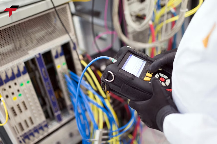
Ladder logic runs the control sequences behind far more equipment than the two worked rungs above. Material-handling conveyor systems, pallet packing and strapping lines, cement batching, beverage bottling and labeling, and hopper or tank level control all run on rung-based logic built from the same contacts, coils, timers and counters covered here. Air and liquid flow and pressure control loops add the arithmetic and comparison instructions from the symbol table onto that same rung structure — a hopper level control loop, for example, reads an analog level input through a comparison instruction and drives a fill-valve output coil once the reading crosses the preset value, the same comparison-to-coil pattern the symbol table covers. Each application differs in which field inputs and outputs are wired in, not in the underlying rung logic.
Common Ladder Logic Applications in Industrial Automation
Where Ladder Logic Fits on a Malaysian PLC Line
Ladder logic on a Malaysian PLC line assumes a brand is already chosen for the panel before either worked rung above gets wired in. On a Malaysian production line, that choice usually comes down to the automation brands already standardised on-site or specified by the machine builder — Mitsubishi PLC, Omron PLC, and other options in the wider PLC category all program the same rung logic covered here, with only the on-screen instruction names differing, as the vendor-naming table above shows.
Frequently Asked Questions
These frequently asked questions cover the comparisons and edge cases engineers raise most often once the rung mechanics, symbol table, and worked examples above are clear. Each answer below builds directly on the rung, rail, and scan-cycle definitions covered earlier.
Is ladder logic still the default PLC language?
Yes, ladder logic remains the most widely used PLC programming language on factory floors, even though a 2019 IEEE Spectrum ranking placed it 50th of 52 general-purpose programming languages. That low general-purpose ranking reflects ladder logic’s narrow, industrial-only use case rather than its standing inside automation, where its rung-and-rail format still outnumbers text-based alternatives for day-to-day PLC programming.
What is the difference between a rung and a rail?
A rail is one of the two vertical lines running down each side of a ladder diagram, supplying logical power; a rung is one horizontal line of contact-and-coil logic connecting between them. A ladder diagram has exactly two rails for its full length but as many rungs as the program needs — each rung is one independent control rule.
Can ladder logic handle analog values?
Ladder logic handles analog values through dedicated comparison and arithmetic instructions added onto a rung, not through the basic contact-and-coil symbols themselves. Analog-heavy control tasks, such as continuous temperature control, are often easier to express in the IEC 61131-3 alternatives Structured Text or Function Block Diagram, which some newer PLCs support alongside ladder logic in the same program.
Do Siemens and Allen-Bradley use the same symbols?
Siemens and Allen-Bradley use the same graphical symbols for ladder logic, but the instruction names differ. Siemens labels the two basic input instructions NO contact and NC contact; Allen-Bradley labels the identical graphical symbols XIC (Examine if Closed) and XIO (Examine if Open), as the vendor-naming table earlier in this article shows for the full instruction set.