
PLC Programming Basics: Languages, Scan Cycle and First Program

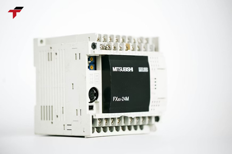
PLC programming is the process of writing the instruction logic that a programmable logic controller (PLC) executes to monitor inputs and control connected machines. Every automated line on a Malaysian factory floor — a palm oil batching skid, a semiconductor handler, a glove-dipping conveyor — runs on this same principle: a small industrial computer reading sensors, comparing that data against a program, and driving outputs in response. Getting PLC programming wrong does not just produce a bug; it produces a stalled line, a mis-filled tank, or a safety interlock that never trips.
This guide covers the five IEC 61131-3 languages engineers use to write that logic, how the scan cycle actually executes a program tens of milliseconds at a time, and a worked traffic-light example that builds your first program from a blank ladder. It targets engineers, technicians, and maintenance staff who are new to PLC programming and need the mechanics explained without marketing filler.
What Is PLC Programming?
PLC programming is the process of writing the instruction logic a programmable logic controller runs to control industrial equipment. A programmer defines how the controller reacts to input signals — a limit switch closing, a pressure sensor crossing a threshold, an operator pressing a start button — by specifying which outputs turn on, off, or change state in response. Automation Ready Panels frames this precisely: PLC programming is “computer code language used to control factory machines or processes,” built from bit logic that resolves to true or false at every rung.
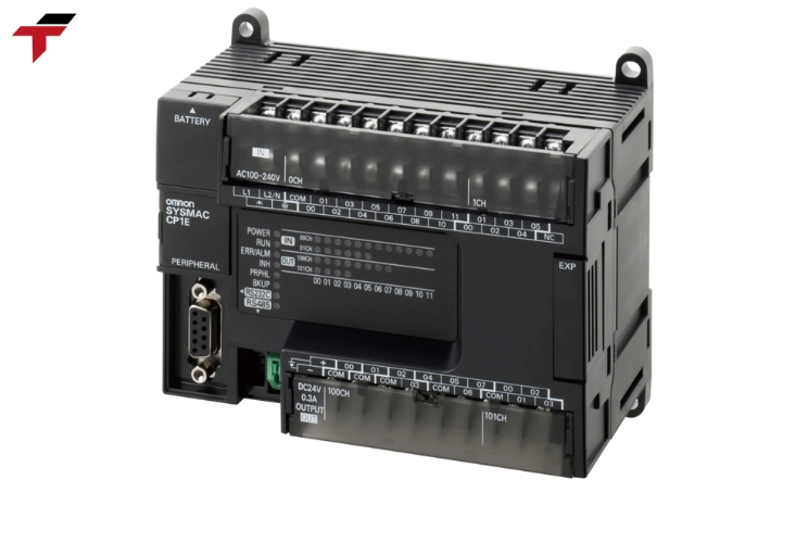
A PLC has three functional parts that make this possible. I/O modules form the bridge between field devices and the controller: input modules collect signals from sensors, switches, and push buttons, while output modules drive relays, valves, motor starters, and alarms. A CPU module, built around a microprocessor, does the actual processing — it energizes or de-energizes outputs based on input states, executes the application program, and manipulates memory. A programming device — a PC, laptop, or handheld unit running vendor software — is where an engineer writes and loads that program.
The CPU itself runs two separate layers of code. The Operating System is the supervisory instruction set loaded at manufacture; it handles startup, interrupt handling, and I/O data updates, and a programmer never edits it directly. The User Program is the only layer available for modification — the logic, timers, and I/O mapping that determine what the PLC actually does on your specific line. Reprogramming a PLC for a new process means rewriting the User Program only, which is also why a logic mistake will not damage the controller’s firmware. How much room that User Program has to grow, though, depends on which of the two PLC hardware types sits on the panel.
Types of PLC Used in Programming: Fixed vs Modular
PLCs fall into two hardware types that shape how programming is structured: fixed and modular. A fixed PLC has a pre-built number of inputs and outputs wired internally, while a modular PLC is built from separate racks and cards that expand independently. The distinction matters for programming because I/O addressing, memory allocation, and how much a program can grow all depend on which type sits on the panel.
Fixed PLCs are the most common type on smaller or portable control systems. They cost less than modular PLCs and suit standalone tasks with a known, unchanging I/O count. Because the processing unit, terminals, and I/O components are wired together internally, a fixed PLC has less memory headroom than a modular unit, and a program written for one fixed model rarely transfers cleanly to another with a different I/O count.
Modular PLCs are built for programs that need to scale. Adding I/O, upgrading memory, or improving the processing unit means adding a card rather than replacing the controller, which is why large-scale operations — a multi-zone palm oil processing line, for example — favor modular architecture. Each module handles a specific job, so isolating a fault in one module does not require stopping the rest of the running program. Fixed or modular, every PLC runs that program the same way once it is loaded — on a repeating scan cycle.
How Does PLC Programming Work? The Scan Cycle
A PLC executes its program on a repeating scan cycle, not continuously like a desktop application. Each pass through the cycle follows a fixed sequence: read the state of every connected input, execute the user program against that input snapshot, write the resulting outputs, then run an internal diagnostic check before the cycle restarts. A full cycle typically takes tens of milliseconds.
This sequencing is what makes ladder logic safe to evaluate top-to-bottom without race conditions. Because the PLC captures every input at the start of the scan rather than reading it mid-execution, program logic only ever sees one consistent snapshot of the plant per pass — a valve position sensor cannot change value halfway through a rung evaluation and produce an inconsistent result.
The scan cycle includes four stages, listed below:
- Read inputs.The CPU samples every connected input device — digital states like a switch being on or off, and analog readings like temperature or pressure — and stores the values in memory.
- Execute the program.The CPU runs the user logic, rung by rung or block by block, against the input values captured in step 1.
- Write outputs.The CPU updates every connected output device — opening a valve, adjusting a motor speed, energizing an alarm — based on what the program calculated.
- Diagnostic check.The CPU runs an internal housekeeping pass to confirm operating conditions are normal before starting the next cycle.
Remote I/O — an external rack connected over a network rather than wired directly to the CPU — adds response-time uncertainty to this cycle, which is why time-critical counting tasks (shaft encoders, high-speed pulse counting) typically use dedicated counter modules instead of relying on scan-cycle timing alone. What actually runs during the “execute the program” step of that cycle is written in one of five standardized languages.

How Does PLC Programming Work? The Scan Cycle
The 5 PLC Programming Languages (IEC 61131-3)
The IEC 61131-3 standard defines five PLC programming languages: Ladder Logic, Structured Text, Function Block Diagram, Sequential Function Chart, and Instruction List. Each language fits a different class of control problem, and the choice usually tracks who is programming rather than which language is objectively “better.” Plant electricians, who already read relay-wiring schematics, default to Ladder Logic. Engineers coming from a software background gravitate toward Structured Text. Process engineers building PID loops reach for Function Block Diagram.
| Language | Best fit | Typical user |
| Ladder Logic (LD) | Discrete on/off machine control | Electricians, maintenance technicians |
| Structured Text (ST) | Math-heavy or data-processing logic | Software-background engineers |
| Function Block Diagram (FBD) | PID loops, analog scaling | Process/chemical engineers |
| Sequential Function Chart (SFC) | Batch or step-ordered processes | Batch process engineers |
| Instruction List (IL) | Legacy or low-memory platforms | Maintaining older systems |
Ladder Logic (LD)
Ladder Logic represents control logic as a series of rungs that mimic relay-wiring diagrams. Each rung evaluates a set of input conditions; when the logic resolves to true, the rung energizes its output. This visual, rung-by-rung structure is why it is the most widely used PLC programming language worldwide — it maps directly onto the physical relay panels electricians already troubleshoot with a multimeter.
Ladder Logic is simple to implement and troubleshoot because it provides visual confirmation of status for most instructions, and its modular rung structure makes logic easy to add or remove without disturbing the rest of the program. The tradeoff shows up in complex applications: once a process involves PID control, flow feedback, or heavy analog manipulation, ladder rungs become difficult to build and read, which is where the other four languages take over.
Function Block Diagram (FBD)
Function Block Diagram represents control logic as interconnected function blocks, resembling a wiring diagram rather than a relay ladder. It was developed with chemical and process applications in mind, and its most common use case is building PID controllers and scaling analog signals — tasks where a Piping & Instrumentation Diagram maps naturally onto connected function blocks.
FBD’s visual editor is flexible and intuitive for laying out complex programming structures that would need many separate rungs in Ladder Logic. The drawback appears at scale: because each programmer lays out blocks differently, large FBD programs become hard to standardize and difficult for another engineer to follow later.
Structured Text (ST)
Structured Text is a text-based PLC programming language that closely resembles C or Pascal, executing sequential lines of code rather than visual rungs or blocks. It gives engineers with a traditional programming background — C, C++, Java, Python — a familiar transition into PLC work, and it handles complex functionality, loops, and case logic more easily than Ladder Logic allows.
Structured Text is standardized across most PLC platforms, which makes it more portable between hardware brands than Ladder Logic or Function Block Diagram. Troubleshooting is the tradeoff: without ladder-style visual cues, diagnosing a Structured Text program on the plant floor takes more code-reading skill, and flexibility without disciplined coding practice makes it easier to introduce errors.
Sequential Function Chart (SFC)
Sequential Function Chart organizes program logic into a defined sequence of steps, each with its own start condition and transition rule. It suits any process with a fixed order of stages — a chemical batching process is the textbook example, where a system checks readiness, fills tanks with measured ingredients, holds a temperature for a set period, then transfers the finished batch onward. Applied to a Malaysian production line, an F&B filling sequence or a palm oil batch process follows the same step-gated pattern.
SFC is a poor fit outside sequential processes, and parallel process flows — multiple steps running at once rather than one after another — are difficult to implement and troubleshoot within an SFC chart.
Instruction List (IL)
Instruction List is a low-level, text-based PLC programming language that resembles assembly code, with each line specifying one instruction, one condition, and one outcome. Its compact, non-graphical format made it a practical choice for handheld programming devices with limited memory in earlier automation platforms.
Instruction List is not available on most current PLC platforms, and it has largely been superseded by Structured Text on newer systems — most engineers today encounter it only when maintaining legacy programs.
PLC programming, so far, breaks down into three connected ideas. A PLC’s I/O modules, CPU, and programming device work together to run a User Program on top of a fixed Operating System. That program executes on a repeating scan cycle — read inputs, execute logic, write outputs, run diagnostics — every few tens of milliseconds. Which of the five IEC 61131-3 languages carries that logic depends on the job: Ladder Logic for discrete on/off control, Structured Text for math-heavy logic, Function Block Diagram for PID loops, Sequential Function Chart for batch sequences, and Instruction List mostly on legacy platforms. The next section puts those pieces together in an actual program.
Instruction List (IL)
Writing Your First PLC Program: A Traffic Light Example
A traffic-light sequence is a standard first PLC program because it uses only three outputs, one input, and the basic rung-evaluation logic Ladder Logic was built for. The example below covers three steps: defining the I/O, building the ladder rungs, then testing the logic before it runs on a physical or simulated PLC.
Step 1: Define Inputs and Outputs
The CPU acts only on signals it has been told to expect, which is why every PLC program starts with an I/O list. A traffic-light program needs one input and three outputs:
- Input:Start pushbutton (Start_PB) — begins the light sequence.
- Output 1:Red light (Red_Out).
- Output 2:Green light (Green_Out).
- Output 3:Yellow light (Yellow_Out).
Three timers manage how long each light stays on: T1 for red, T2 for green, and T3 for yellow. Each timer’s preset value depends on the intended cycle length, which the programmer sets during commissioning rather than in the code itself.
Step 2: Build the Ladder Logic Rung
Each ladder rung reads its input condition and, if the condition is true, energizes its output. With I/O defined, the four rungs below apply that scan-cycle logic to the traffic-light sequence.
- Rung 1:Start_PB energizes Red_Out and starts timer T1.
- Rung 2:When T1 times out, Red_Out de-energizes, Green_Out energizes, and timer T2 starts.
- Rung 3:When T2 times out, Green_Out de-energizes, Yellow_Out energizes, and timer T3 starts.
- Rung 4:When T3 times out, Yellow_Out de-energizes, and the program returns to Rung 1 to repeat the sequence.
Each rung follows the same rule Ladder Logic uses throughout: evaluate the condition on the left, and if it resolves true, execute the output instruction on the right. Chaining timer outputs this way is what turns four simple rungs into a repeating, self-resetting sequence.
Step 3: Test and Download the Program
Before loading logic onto a physical PLC, most programming software includes a simulation or offline test mode that steps through the scan cycle without connected hardware — this catches rung-order mistakes (like forgetting to reset a timer) before they reach the floor. Once the simulated sequence cycles correctly through red, green, and yellow, the programming device downloads the User Program to the PLC’s memory, and the controller begins executing it on its normal scan cycle. That programming device — the tool that wrote, tested, and downloaded the logic — is worth a closer look on its own.
PLC Programming Tools
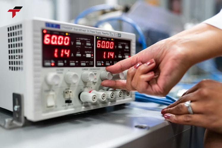
A programming device — a PC, laptop, or dedicated handheld unit — is the tool required to write, simulate, and download a PLC program. Most PLC manufacturers pair their controllers with a proprietary software package (comparable in role to Mitsubishi PLC programming software or an Omron PLC development environment), and that software typically supports several of the five IEC 61131-3 languages within one interface, letting a programmer mix Ladder Logic for discrete control with Structured Text for data handling in the same project.
Once a program is transferred to the PLC’s non-volatile memory, the programming device can disconnect entirely — the controller runs its scan cycle independently, without needing a continuous connection to the tool that wrote the logic. What that independent controller actually does next depends on the application it was programmed for.
PLC Programming Tools
Common PLC Programming Applications
PLC programming applications span most stages of Malaysian manufacturing, from semiconductor handling in Penang to palm oil processing and F&B filling lines. The pattern across applications stays consistent: a program monitors inputs, applies logic, and drives outputs — the specifics change by industry.
- Material handling and conveyors— starting, stopping, and sequencing conveyor sections based on part-present sensors.
- Batch and process control— Sequential Function Chart-driven filling, mixing, and temperature-hold sequences for F&B and palm oil processing.
- Machine safety interlocks— Ladder Logic-based emergency-stop and guard-door circuits that halt equipment on a fault condition.
- Motion and drive control— Function Block Diagram-based coordination between a PLC and connected servo drive Malaysia or inverter Malaysia
- Data logging and reporting— Structured Text routines that capture production counts or fault codes for review.
Frequently Asked Questions About PLC Programming
These four questions cover the terms and comparisons that come up most often once the core mechanics — I/O structure, scan cycle, and the five languages — are already clear.
What does PLC stand for?
PLC stands for Programmable Logic Controller — an industrial computer designed to control machines and processes through custom programming rather than fixed wiring.
What is the difference between a PLC and a PAC?
A PAC (Programmable Automation Controller) extends the same IEC 61131-3 languages a PLC uses but adds PC-class processing, letting a single controller handle motion, process, and drive control together instead of requiring separate discrete-logic PLCs. The five programming languages transfer directly between the two platforms — the programming skill is not PLC-specific.
Can Python be used for PLC programming?
Yes. Some newer PLC and PAC platforms allow supplementary scripting in Python alongside the five IEC 61131-3 languages, mainly for data-handling or analytics tasks. This capability is vendor-added and falls outside the IEC 61131-3 standard itself.
Which PLC programming language should beginners learn first?
Most PLC training resources recommend starting with Ladder Logic before moving to Structured Text or Function Block Diagram. Its visual rung structure is the easiest to troubleshoot without a software background, and it remains the most common language on the plant floor across PLC brands.
________________________________________
PLC programming starts with the same three concepts covered here: what the controller’s I/O and CPU structure actually do, how the scan cycle turns that structure into a repeating read-execute-write loop, and which of the five IEC 61131-3 languages fits the job in front of you. A traffic-light program is a small example, but it exercises the identical rung-evaluation logic that runs conveyor interlocks, batch sequences, and motion control on a production floor. For PLC hardware to run that logic on — Mitsubishi PLC, Omron PLC, Panasonic PLC, and Xinje PLC models — see the PLC Malaysia category.