
What Is a Programmable Logic Controller? Architecture and Components


A programmable logic controller (PLC) is a ruggedised industrial computer that reads inputs, executes a stored control program, and writes outputs to actuators and motors. It is the core decision-making hardware behind most automated production lines. Manufacturers moved to the programmable logic controller because relay logic could not survive the reconfiguration cycles of modern production: rewiring a relay panel took days, while reloading a PLC program takes minutes. Mitsubishi, Omron, Siemens, Panasonic, and Allen-Bradley each build a programmable logic controller around the same core architecture, even though the programming software differs by brand.
This guide breaks the programmable logic controller down into its five hardware components, the three-step scan cycle every PLC runs, the IEC 61131-3 programming languages including ladder logic and function block diagram, and the difference between fixed and modular PLC types. It closes with how a PLC integrates with a human-machine interface and which PLC brands Flextech Industrial stocks for system integrators across Selangor, Penang, and Johor.
Programmable Logic Controller — Definition and Origin
A Programmable Logic Controller (PLC) is an industrial computer that has been ruggedised and adapted for the control of manufacturing processes — assembly lines, machines, robotic devices, or any process requiring high reliability, ease of programming, and fault diagnosis. A PLC differs from a desktop computer in the same category of device (both are, at their core, microprocessor-based systems) mainly in construction: a PLC tolerates dust, moisture, heat, vibration, and electrical noise that would fail standard office-grade hardware, and it runs a real-time operating system where output results must be produced within a limited time window after an input change.
The programmable logic controller was invented to replace hard-wired relay logic. In 1968, GM Hydramatic — the automatic transmission division of General Motors — issued a request for proposals for an electronic replacement for relay panels, based on a specification written by engineer Edward R. Clark. Bedford Associates won the contract and delivered the first PLC in 1969: the Modicon 084, named for being the company’s eighty-fourth project. Dick Morley, who worked on that project, is widely credited as the PLC’s inventor.
In a parallel development at Allen-Bradley, Odo Josef Struger is credited with coining the “PLC” acronym itself, adding “Logic” to distinguish the device from the newly popularised “PC” (personal computer) of the early 1980s.
A relay panel executes logic through physical wiring — changing the sequence means rewiring the panel. A PLC executes the identical logic as a stored program, so changing the sequence means loading new code. That single shift from hardware logic to stored-program logic is what makes the programmable logic controller the standard control device across semiconductor, palm oil, food and beverage, and rubber manufacturing lines in Malaysia today. That shift is only possible because of what happens inside the PLC on every cycle it runs.
How a PLC Works — Reading Inputs, Executing Logic, Writing Outputs
A PLC’s operation runs on a repeating scan cycle with three steps: read inputs, execute the program, write outputs.
- Read inputs.The PLC captures the current state of every connected input device — sensors, switches, and operator controls — and freezes those values in memory for the duration of the cycle.
- Execute the program.The stored control program evaluates the frozen input states against the programmed logic, in sequence, to determine what each output should do.
- Write outputs.The PLC updates every connected output device — motors, valves, indicator lamps, alarms — to match the result of the program logic.
A full scan cycle typically completes in tens of milliseconds, and the PLC restarts the cycle immediately after writing outputs. Many PLCs add a fourth housekeeping step — an internal diagnostic check confirming the system is within normal operating conditions — before the next read-inputs pass begins.
PLC inputs and outputs fall into two categories. Discrete (digital) I/O can only take an on or off value — a limit switch or a photoelectric sensor is a typical discrete input, and a motor contactor or an indicator lamp is a typical discrete output. Analog I/O carries a value across a continuous range — a 4-20 mA current loop or a 0-10 V signal represents pressure, temperature, flow, or weight, and the PLC converts that signal into an integer value the program can read. A production line commonly mixes both: a photoelectric sensor (discrete) confirming a part is present, alongside a temperature transmitter (analog) reporting a process value. Reading and writing those signals is only possible because five hardware components work together inside the PLC on every scan.
PLC Architecture — Core Hardware Components
A programmable logic controller is built from five hardware components, each with a distinct role in the read-execute-write cycle described above. Every one of the five has to be present, in some form, for the PLC to function at all — whether it ships as a single fixed housing or a modular rack.
- Processor unit (CPU):Interprets inputs, executes the control program stored in memory, and sends output signals. This is the component most engineers mean when they refer to “the PLC” in conversation, though it cannot function without the other four components.
- Power supply unit:Converts incoming AC voltage to the DC voltage the processor, memory, and I/O circuits require. On a modular PLC, the power supply is a separate rack module; on a fixed (brick) PLC, it is built into the same housing as the processor.
- Memory unit:Stores the control program and the data captured from inputs during each scan. PLC programs are typically held in non-volatile flash memory or battery-backed-up RAM, so the program survives a power interruption without needing to be reloaded.
- Input/output (I/O) interface:The physical terminals where the PLC receives signals from field devices (sensors, switches) and sends signals to field devices (motors, valves, relays). I/O interface design — the number of points and the mix of discrete versus analog — is the single factor that most determines which PLC type suits a given machine.
- Communications interface:Sends and receives data over industrial network protocols — Modbus, EtherNet/IP, PROFINET — to link the PLC with other PLCs, a SCADA system, or a human-machine interface.
A programming device is required to write the control program and download it into the PLC’s memory, but it is not part of the PLC’s own hardware architecture — it connects temporarily during programming and disconnects during normal operation. How these five components are physically packaged — into one housing or across several rack modules — is what defines a PLC’s mechanical design.

PLC Architecture — Core Hardware Components
PLC Modules — Fixed and Expandable I/O
PLC modules fall into two mechanical categories: the fixed (brick) design and the modular (rack) design, and the choice between them sets the ceiling on how far a PLC’s I/O count grows after installation.
A fixed PLC (also called a brick) integrates the processor, memory, power supply, and a pre-set number of I/O points into one compact housing. Fixed PLCs are the most common PLC type on the market — smaller, more affordable, and adequate for standalone machines with a known, unchanging I/O count. Most fixed PLCs still accept additional expansion modules, so a fixed PLC is not necessarily locked to its built-in I/O count, only more limited in how far it can scale.
A modular PLC replaces the single housing with a chassis (rack) that accepts separate PLC modules for each function: a power supply module, a processor module, and any number of I/O modules or communication modules selected for the application. Common PLC module types include:
- Digital I/O modules— discrete input or output points for switches, sensors, and on/off actuators
- Analog I/O modules— input or output points for continuous-range signals (temperature, pressure, flow)
- Communication modules— add a network protocol (EtherNet/IP, PROFINET, Modbus) where the base processor lacks a built-in port
- Specialty modules— high-speed counter modules for shaft encoders, or precision timing modules where the scan cycle itself is too slow for the application
Several racks can be managed by a single processor over a high-speed serial I/O link, distributing PLC modules across a large plant floor without running every wire back to one central panel. This is the mechanism that lets a modular PLC scale from a few hundred I/O points to several thousand without changing the processor. That same I/O capacity is also what separates one PLC type from another.
Types of Programmable Logic Controllers
Programmable logic controller types are classified by I/O capacity and mechanical design, which in turn determines cost and the scale of application each type suits.
| PLC Type | I/O Capacity | Design | Typical Use |
| Micro / Nano PLC | 8-32 I/O points | Fixed | Single machine, standalone task |
| Compact PLC | Tens to ~100 I/O points | Fixed, with expansion modules | Small production line, packaging machine |
| Modular PLC | 500+ I/O points | Rack-based, expandable | Large plant floor, multi-zone process |
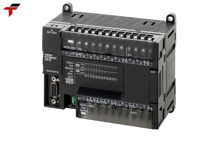
Micro and nano PLCs — the Mitsubishi FX-series or Omron CP1E, for example — cover the 8 to 32 I/O range and typically run RM600-2,500 (USD130-535) in the Malaysian market. Compact PLCs sit in the RM2,500-15,000 (USD535-3,200) range, still fixed-body but expandable with add-on I/O modules. Once a project’s I/O requirement approaches roughly 512 points, a modular PLC — Mitsubishi FX5U, Omron CJ2M, Siemens S7-1200/S7-1500, or Panasonic FP7 — becomes the more practical choice, with pricing from RM15,000 (USD3,200) upward depending on the module count and processor tier. These figures are indicative ranges for planning purposes; exact PLC pricing depends on the specific module configuration and brand.
Fixed PLCs are harder to repair or expand because the processor, terminals, and I/O are wired internally, but this same construction keeps them compact and lower-cost. Modular PLCs cost more and take more panel space, but isolating each function to its own module makes fault diagnosis and expansion considerably faster on a line that cannot tolerate long downtime.
Recap: Architecture, Modules, and Types So Far
This recap ties together the PLC architecture, modules, and types covered so far. A programmable logic controller is an industrial computer built from five hardware components — processor unit, power supply, memory, I/O interface, and communications interface — running a repeating scan cycle of read inputs, execute program, write outputs. Its mechanical design is either fixed (brick), with I/O built in and limited expansion, or modular (rack), with separate digital I/O, analog I/O, and communication modules added as needed. I/O capacity is what separates a micro/nano PLC (8-32 points) from a compact PLC (up to roughly 100 points) from a modular PLC (500+ points), and that capacity, more than any other single factor, drives which PLC type and price band suits a given machine or line. The next sections cover how a PLC is programmed and how it fits into a wider automation system.

Types of Programmable Logic Controllers
PLC Programming Languages — Ladder Logic to Function Block Diagram
A programmable logic controller runs on programmable logic controller software written in one of five languages standardised under IEC 61131-3. Two are textual — Structured Text and the now-deprecated Instruction List — and three are graphical: Ladder Diagram, Function Block Diagram, and Sequential Function Chart.
Ladder logic (Ladder Diagram) remains the most widely used PLC programming language on factory floors. It represents control logic as rungs between two vertical rails, mirroring the layout of a relay wiring diagram — a format electricians and maintenance engineers could read without learning a general-purpose programming language. Ladder logic handles binary, on/off control well but becomes clumsy for continuous analog calculations.
Function block diagram (FBD) addresses that gap. Instead of contacts and coils on a rung, function block diagram programming connects pre-built functional blocks — timers, counters, PID loops, arithmetic operations — with signal-flow lines, similar to an electronic circuit schematic. Function block diagram PLC programming is common wherever a process involves continuous control (temperature, flow, pressure) rather than simple on/off sequencing, since expressing a PID loop or an analog scaling calculation in ladder rungs is considerably more awkward than wiring the equivalent function blocks.
Structured Text, a textual language resembling Pascal, suits complex mathematical operations, loops, and array handling that ladder logic and function block diagram both handle poorly. Sequential Function Chart organises a program into steps and transitions, matching processes that move through a defined sequence of stages — a batching or filling process, for example.
PLC programs are never fully interchangeable between manufacturers, even when both use the identical IEC 61131-3 language, because I/O addressing, memory organisation, and instruction sets differ by brand. A ladder logic program written for a Mitsubishi FX-series processor requires re-mapping — not a simple file transfer — before it will run on a Siemens S7-1200. Whichever language runs inside the PLC, an operator still needs a way to see what that program is doing in real time.
PLC and Human-Machine Interface (HMI) Integration
A PLC executes control logic, but it needs a way to let an operator see what that logic is doing and intervene when required — that is the role of the human-machine interface (HMI). A simple PLC system may rely on physical buttons and indicator lamps for this purpose; a plc human machine interface setup on a modern line uses a graphical touchscreen connected to the PLC over a communications interface, displaying real-time values and accepting operator input such as start/stop commands or setpoint changes.
The PLC remains the decision-making hardware in this pairing: it holds the control program, executes the scan cycle, and drives the outputs. The HMI is a window into that process, not a substitute for it — removing the HMI does not stop the PLC from running, though it removes the operator’s visibility into the running process. Malaysian manufacturers commissioning a new line typically pair a PLC Malaysia controller with an HMI Malaysia screen from the outset, since the two are specified and wired together as a single control station. That control station, in turn, is only one part of a larger automation system.
Where a PLC Fits in an Industrial Automation System
A PLC is one layer inside a broader industrial automation system, positioned between field devices on the plant floor and higher-level monitoring systems. Sensors and actuators sit below the PLC, connected through its I/O interface. A SCADA (Supervisory Control and Data Acquisition) system typically sits above the PLC, aggregating data from multiple PLC systems across a plant for centralised monitoring, trending, and reporting — the PLC still performs the real-time control locally, while SCADA handles supervision and historical logging.
Communication between these layers runs over industrial network protocols — Modbus, EtherNet/IP, PROFINET are common choices — carried through the PLC’s built-in or add-on communications interface. Some PLC systems also support peer-to-peer communication directly between processors, allowing separate sections of a complex process — a filling line and a downstream capping line, for example — to run individual control locally while still coordinating timing over the shared network link. This layered structure plays out differently across Malaysia’s manufacturing sectors, depending on what each process actually controls.

Where a PLC Fits in an Industrial Automation System
Programmable Logic Controller Applications in Malaysian Manufacturing
Malaysian manufacturing spans several sectors where a programmable logic controller is the standard control device, though the I/O count, module selection, and environmental rating differ by industry.
Semiconductor manufacturing (Penang, Selangor): Back-end processes — die bonding, wire bonding, wafer handling — run on modular PLC systems with high I/O density and fast scan times to keep pace with cleanroom equipment cycle times. Communication modules linking multiple PLC racks over EtherNet/IP or PROFINET are standard on multi-station equipment.
Palm oil processing: Screw press drives, steriliser controls, and conveyor sequencing rely on PLC systems built for humid, high-temperature environments, typically specified with a higher-rated enclosure than office or cleanroom installations require.
Rubber and glove manufacturing: Conveyor indexing through oven zones runs on PLC-controlled timing sequences, where consistent scan-cycle timing directly affects dwell time and, by extension, product thickness uniformity.
Food and beverage: Filling, capping, and labelling lines combine discrete I/O for machine sequencing with analog I/O for flow and level control, commonly paired with an HMI for recipe changeover between product runs.
Flextech Industrial Supplies stocks PLC hardware — Mitsubishi, Omron, Siemens, Panasonic, Allen-Bradley, Xinje, and Autonics — for system integrators and maintenance teams specifying or replacing controllers across these sectors, with local support in Selangor, Penang, and Johor. Matching the right brand to each of these applications comes down to a short list of selection criteria.
Choosing a PLC Brand for an Automation Project
Selecting a PLC comes down to matching I/O count, communication protocol, and programming software to the application before comparing brand and price.
- I/O count:Confirm the total discrete and analog points required now, plus expected growth, before choosing between a fixed and a modular PLC.
- Communication protocol:Confirm what the existing HMI, SCADA system, or neighbouring PLC already uses — Modbus, EtherNet/IP, or PROFINET — since mismatched protocols add a gateway device and cost to the project.
- Programming software familiarity:A maintenance team already trained on Mitsubishi’s GX Works or Siemens’ TIA Portal will service and troubleshoot that brand’s PLC faster than an unfamiliar one, which is often a stronger deciding factor than a small price difference between brands.
- Environmental rating:Standard industrial enclosure ratings suit most factory floors; humid or washdown environments — palm oil, food processing — call for a higher IP rating on the PLC enclosure.
Flextech Industrial carries Mitsubishi PLC, Omron PLC, Panasonic PLC, and Xinje PLC ranges, alongside Siemens and Allen-Bradley controllers, sourced from manufacturers and reputable international agents for Malaysian system integrators and procurement teams.
Choosing a PLC Brand for an Automation Project
Frequently Asked Questions About Programmable Logic Controllers
These five questions cover what a PLC controller does, how PLC logic runs on every scan cycle, and how a PLC differs from related hardware such as a desktop computer or a stand-alone HMI panel.
What is a PLC controller used for?
A PLC controller is used to automate a manufacturing or industrial process — reading input signals from sensors and switches, running a stored control program, and driving output devices such as motors, valves, and indicator lamps. Typical uses range from a single conveyor or packaging machine to an entire production line coordinating dozens of connected devices.
What is PLC logic?
PLC logic is the control program stored inside a programmable logic controller’s memory, written in one of the IEC 61131-3 languages — most commonly ladder logic — and evaluated on every scan cycle to determine the state of each output based on the current state of each input.
Is a PLC the same as a computer?
A PLC is a specialised industrial computer, not a general-purpose one. It shares the same basic microprocessor-based architecture as a desktop computer — CPU, memory, input/output — but is ruggedised for industrial environments and runs a real-time operating system designed for predictable, time-limited control cycles rather than general computing tasks.
What are the main types of PLC modules?
The main PLC module types are digital I/O modules (for on/off signals), analog I/O modules (for continuous-range signals such as temperature or pressure), and communication modules (for network protocols such as EtherNet/IP or PROFINET). Specialty modules — high-speed counters or precision timers — cover applications where the base scan cycle is too slow.
What programming language does a PLC use?
The programming language a PLC uses most commonly is ladder logic, but the IEC 61131-3 standard defines four additional languages: Function Block Diagram, Structured Text, Sequential Function Chart, and the now-deprecated Instruction List. Function Block Diagram is typically preferred over ladder logic for continuous analog control such as PID loops.