
How a VFD Works: Rectifier, DC Bus, IGBT Inverter Stage

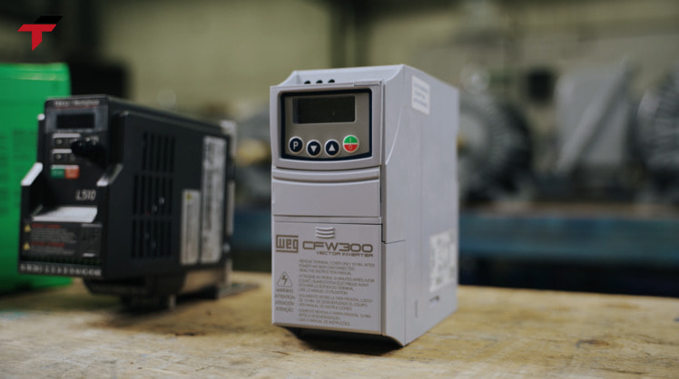
A VFD inverter converts fixed-frequency AC mains power into variable-frequency AC power through three internal stages: a rectifier, a DC bus, and an IGBT inverter stage. This variable frequency drive architecture is what lets a single control device change an AC motor’s speed continuously, instead of running it at one fixed speed set by the mains frequency. Malaysian production lines in semiconductor assembly, palm oil processing, food and beverage, and rubber and glove manufacturing rely on this three-stage conversion to control pumps, fans, conveyors, and compressors without oversized mechanical throttling.
This guide walks through each of the three conversion stages in order — rectifier, DC bus, IGBT inverter stage — then covers what a VFD does to motor voltage and frequency, how VFD-driven pump applications save energy, and how Schneider, Delta, and Flextech-carried inverter brands compare on the Malaysian market.
VFD Inverter Definition
A VFD inverter — variable frequency drive — is a power electronics device that controls an AC motor’s speed and torque by changing the frequency and voltage of the electrical power supplied to it. The term “VFD inverter” is used interchangeably with “variable frequency drive” and “inverter drive” in most Malaysian industrial catalogues and technical documentation, though “inverter” strictly refers to only the final conversion stage inside the device, covered in detail below.
Before VFDs became standard, controlling AC motor speed meant either accepting a fixed speed set by the 50Hz mains frequency, or using mechanical methods — throttling valves, dampers, or gearboxes — to control the driven load instead of the motor itself. A VFD replaces that mechanical control with electronic frequency control at the motor’s power supply, which is both more precise and, in loads like pumps and fans, substantially more energy-efficient. That electronic frequency control happens inside three internal conversion stages, covered next.
How a VFD Works: The 3-Stage Power Conversion
A VFD’s internal architecture consists of three distinct sub-systems arranged in sequence: a rectifier bridge converter, a DC bus (DC link), and an inverter switching stage. Power flows through all three stages every time the VFD runs a motor, converting fixed AC in, to DC, to variable-frequency AC out.
Stage 1 — Rectifier: AC to DC
The rectifier stage is the VFD’s input stage, and its job is to convert the incoming three-phase AC mains supply into DC. The most common rectifier configuration in a standard VFD is a three-phase, six-pulse, full-wave diode bridge — a fixed arrangement of diodes that conducts current in only one direction, producing a pulsating DC output from the AC input waveform. Because diode rectifiers are passive (no active switching), they are the simplest and least expensive rectifier type, and they remain the default choice in most industrial VFDs sized for pumps, fans, and general motor control.
Some VFD designs use an active rectifier built from IGBTs instead of diodes, which allows the drive to feed energy back into the mains supply during braking — a feature relevant to regenerative applications such as cranes, elevators, and centrifuges, but not required for the pump and fan loads that make up most Malaysian industrial VFD installations.
Stage 2 — DC Bus: Filtering and Energy Storage
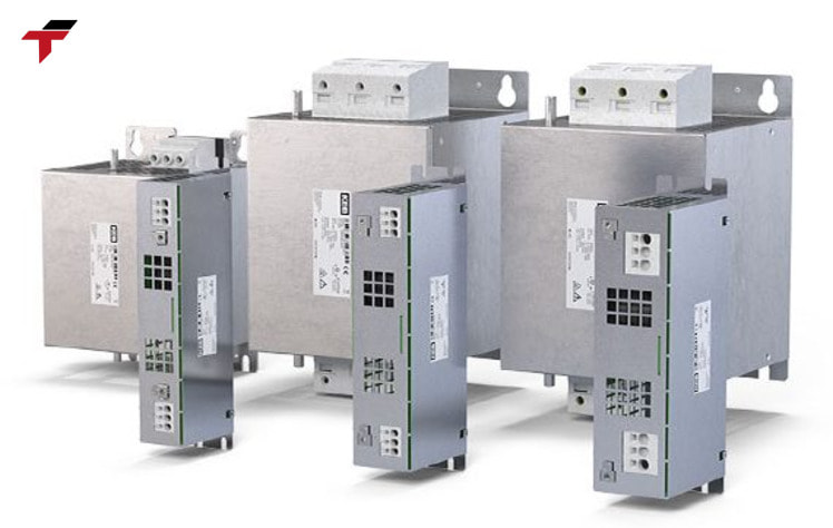
The DC bus — also called the DC link — sits between the rectifier and the inverter stage, and its role is to smooth the rectifier’s pulsating DC output into a stable DC voltage before it reaches the inverter switching devices. A bank of capacitors forms the core of the DC bus in the voltage-source inverter (VSI) topology used by the large majority of VFDs on the market; these capacitors absorb the ripple in the rectified DC voltage and provide a stiff, stable DC supply to the inverter stage.
The DC bus also functions as a short-term energy reservoir. If mains supply dips briefly, the charge stored in the DC bus capacitors can keep the drive running through the interruption; conversely, during motor deceleration, the motor can feed energy back into the DC bus faster than the rectifier draws it from the mains, which is why VFDs controlling high-inertia loads or requiring fast stops are frequently fitted with a braking resistor connected across the DC bus — the resistor dissipates that excess regenerated energy as heat, preventing the DC bus voltage from rising to a level that trips the drive on overvoltage fault.
How a VFD Works: The 3-Stage Power Conversion
Stage 3 — IGBT Inverter Stage: DC to Variable-Frequency AC
The IGBT inverter stage is the final and most electronically active stage of a VFD, and it is what makes the “variable frequency” part of variable frequency drive possible. This stage takes the stable DC voltage from the DC bus and switches it back into AC — but unlike the fixed 50Hz output a simple inverter would produce, the VFD’s inverter stage generates an AC output at whatever frequency the control circuit commands.
The insulated-gate bipolar transistor (IGBT) has been the dominant switching device used in this stage since the early 1980s, replacing older thyristor-based designs in the large majority of VFDs manufactured today. The IGBT inverter stage switches DC voltage on and off at high frequency using pulse-width modulation (PWM) — rapidly varying the width of each voltage pulse so that the average output approximates a sine wave at the target frequency. Three pairs of IGBTs, switching in a coordinated sequence, produce a three-phase AC output with each phase 120 electrical degrees apart, matching the three-phase supply a standard industrial AC motor expects.
Because the inverter stage controls both the frequency and the corresponding voltage magnitude of its output, it is this stage — not the rectifier or DC bus — that directly sets the connected motor’s speed.
VFD Power Conversion Stages at a Glance
The table below summarises the three VFD power conversion stages side by side, from AC input to variable-frequency AC output.
| Stage | Function | Core Component | Conversion |
| 1. Rectifier | Convert AC mains to DC | Diode bridge (or active IGBT rectifier) | AC → DC |
| 2. DC Bus (DC Link) | Filter ripple, store short-term energy | Capacitor bank (+ braking resistor if fitted) | DC smoothing |
| 3. Inverter | Generate variable-frequency AC output | IGBT switching devices, PWM control | DC → variable AC |
Summary So Far
A VFD inverter converts AC to DC in the rectifier stage, smooths and stores that DC in the DC bus, then switches it back into AC at a controlled frequency in the IGBT inverter stage. This “AC-DC-AC” conversion path is what separates a variable frequency drive from a simple fixed-frequency inverter, and it is the IGBT inverter stage specifically that determines the frequency — and therefore the speed — delivered to the connected motor. How that frequency change actually controls motor speed and torque is covered next.
VFD Motor Control — Voltage, Frequency and Torque
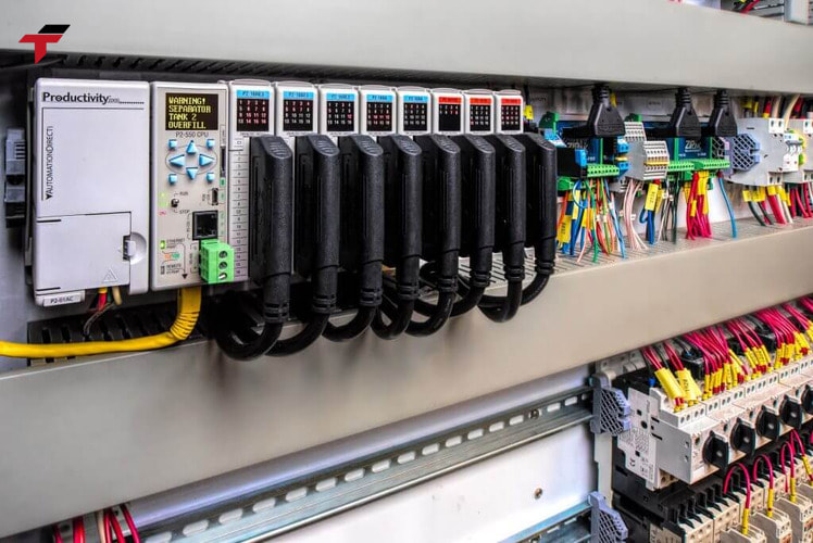
A VFD motor control strategy is built around one core relationship: an AC motor’s synchronous speed is directly proportional to the frequency of its power supply. Reduce the frequency the VFD’s inverter stage delivers, and the motor slows down; increase it, and the motor speeds up — all without changing the motor itself.
Frequency alone is not enough, though. Standard AC induction motors are also designed to run at a matching Volts-per-Hertz (V/Hz) ratio, so as the VFD reduces frequency to slow the motor, it must proportionally reduce output voltage as well, or the motor’s magnetic core saturates and the motor overheats. In Malaysia, where the TNB (Tenaga Nasional Berhad) industrial supply standard is 415V three-phase at 50Hz, a VFD’s V/Hz ratio for a standard 415V/50Hz motor works out to roughly 8.3 V/Hz — the VFD holds this ratio constant across most of its speed range to keep motor torque consistent from low speed up to the motor’s rated (base) frequency.
This is what makes vfd motor control fundamentally different from older speed-control methods that adjusted current or used mechanical gearing: a VFD adjusts the motor’s actual electrical supply, giving continuous, steppless speed control from a small percentage of rated speed up to — and in some applications beyond — the motor’s rated frequency, while a correctly sized VFD also provides overcurrent, overvoltage, and overload protection functions that a fixed-speed motor starter does not. Centrifugal pumps are where this speed control translates most directly into measurable energy savings, covered next.
VFD Motor Control — Voltage, Frequency and Torque
Variable Frequency Drive Pump Applications
Variable frequency drive pump installations account for the large majority of VFD deployments worldwide — roughly three-quarters of all VFD deployments control this category of centrifugal load — and the reason is a well-established relationship between motor speed and energy consumption on these specific load types: cutting a centrifugal pump’s speed by around 20% typically cuts its energy consumption by roughly 50%, because pump power demand scales with the cube of speed rather than linearly.
Before VFDs were standard, controlling a pump’s flow rate meant running the motor at full speed and throttling the output with a valve. That approach wastes the energy difference between what the motor produces at full speed and what the throttled valve actually lets through. A VFD instead slows the pump motor itself to match the required flow — a pump motor rated at 1,450 RPM running 20% slower turns at roughly 1,160 RPM — converting wasted throttling energy into real savings, which is why VFD retrofits on existing pump and fan systems typically pay back their installation cost within 6 to 12 months.
VFDs also change how a pump motor starts. A motor started directly across the line (DOL) draws an inrush current of roughly 500-600% of its full-load current (FLC) for the first few cycles — a demand spike that stresses motor windings, mechanical couplings, and the electrical supply. A VFD instead ramps the motor up gradually, limiting starting current to around 150% of FLC, which reduces mechanical stress on the pump, coupling, and piping system at every start rather than only during commissioning. Which VFD delivers this control depends on the manufacturer, so brand and specification are covered next.
VFD Inverter Brands: Schneider, Delta and Flextech-Carried Options
The Malaysian industrial market includes VFD inverter products from a wide range of manufacturers, and brand selection in practice depends on the installed control system on a given line, procurement relationships, and application requirements rather than one brand being categorically superior across every use case.
Schneider Electric VFD products are a common specification in Malaysian industrial facilities, with the Altivar Process 630 series spanning a power range of roughly 0.75 kW to 500 kW (approximately 1 HP to 670 HP) across 200-240V, 380-480V, and 500-690V three-phase input voltage classes, rated for an ambient operating temperature of approximately -10°C to 50°C (14°F to 122°F) — a range that comfortably covers typical Malaysian factory floor conditions without additional derating in most installations. Delta VFD products are similarly established in the regional market, generally specified alongside Delta’s broader automation product line where a facility has already standardised on Delta components elsewhere in its control system.
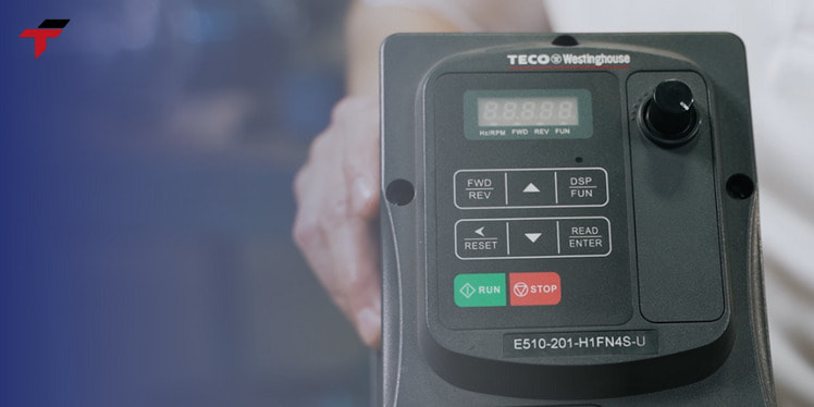
Flextech Industrial’s own inverter Malaysia range is carried from Mitsubishi, Panasonic, Siemens, Toshiba, Xinje, and NAIS — brands chosen to match the PLC and HMI ecosystems most commonly installed on Malaysian production lines Flextech supports, since specifying a VFD from the same manufacturer as an existing PLC often simplifies communication setup and spare-parts sourcing. Flextech is not an authorised distributor for any of these brands; parts are sourced directly from manufacturers and reputable international agents, with local warranty support provided independently of the manufacturer’s own warranty terms.
VFD Inverter Brands: Schneider, Delta and Flextech-Carried Options
Frequently Asked Questions
The three-stage conversion, motor control, and brand comparison are covered above; these questions address terminology and sizing points that come up most often once a VFD inverter is already being specified.
What is the difference between a rectifier and the inverter stage in a VFD?
The rectifier is the VFD’s input stage, converting incoming AC mains power into DC. The inverter stage is the output stage, converting that DC back into AC at a controlled, variable frequency to drive the motor. The two stages perform opposite conversions and sit at opposite ends of the DC bus in between them.
Why does a VFD need a DC bus capacitor?
The DC bus capacitor bank smooths the pulsating DC output from the rectifier into a stable voltage before it reaches the IGBT inverter stage, and it also stores short-term energy — buffering brief mains dips and absorbing energy the motor feeds back during deceleration. Without adequate DC bus capacitance, the inverter stage would receive an unstable DC supply and produce a distorted AC output.
Is a VFD inverter the same thing as an “inverter drive”?
Yes — “inverter drive” and “VFD inverter” both refer to the same type of device: a variable frequency drive that uses an IGBT inverter stage to control AC motor speed. The naming difference is regional and catalogue-specific rather than a difference in the underlying technology.
Can a VFD inverter control any AC motor?
A VFD is designed to control standard three-phase AC induction and synchronous motors, and most VFDs on the market are sized and rated for this motor category. Confirming the motor’s rated voltage, frequency, and full-load current against the VFD’s output rating — and checking whether the motor is rated for inverter duty — remains a necessary step before pairing a specific motor with a specific VFD model.