VFD Harmonics and EMI: Causes, Effects, and Solutions
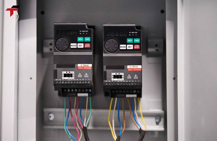
VFD harmonics originate at the input rectifier stage, where variable frequency drives convert AC voltage to DC – drawing non-sinusoidal current from the mains and injecting harmonic frequencies back into the electrical distribution network. Left unmanaged, VFD harmonics overheat motors and transformers, trigger nuisance breaker trips, and accelerate capacitor bank failure. In facilities running multiple drives simultaneously – common in rubber glove production lines, palm oil processing plants, and semiconductor facilities across Malaysia – cumulative harmonic loading can push Total Harmonic Distortion (THD) beyond the IEEE 519-2014 limit, exposing the site to utility penalties and equipment degradation.
This article covers how VFDs generate harmonic distortion at the 6-pulse rectifier stage, the three EMI pathways that compound the problem beyond what harmonic filters alone address, IEEE 519-2014 compliance thresholds for Malaysian industrial facilities, mitigation solution tiers from passive line reactors to active harmonic filters, and a decision framework for selecting the right approach.
How VFDs Generate Harmonic Distortion
The 6-Pulse Rectifier and Non-Linear Current Draw
VFD harmonics originate at the 6-pulse rectifier stage, where non-linear current draw begins: a diode bridge converts incoming AC voltage to DC by pulling current in pulses rather than the continuous sinusoidal flow of a linear load. Resistive and inductive loads draw current in phase with supply voltage; the 6-pulse rectifier does not, producing a waveform that deviates from the fundamental 50 Hz sine wave.
The non-sinusoidal current contains harmonic components at integer multiples of the fundamental frequency. For a 6-pulse rectifier, the dominant harmonic orders are the 5th (250 Hz), 7th (350 Hz), 11th (550 Hz), and 13th (650 Hz). These harmonic currents propagate back into the electrical distribution network, distorting the voltage waveform shared by every load on the same bus.
Other non-linear loads – arc furnaces, UPS systems, switched-mode power supplies – produce harmonics through the same mechanism. VFDs are frequently the dominant source in manufacturing facilities because of their power rating and quantity.
How DC Bus Capacitors Generate Mainline Current Pulses
The 6-pulse rectifier charges a bank of DC bus capacitors, which smooth the rectified voltage and supply energy to the IGBT inverter output stage. Once the capacitors reach the DC bus voltage level, current from the supply stops flowing. Current resumes only when the incoming AC sine wave rises above the DC bus voltage – which occurs near the peaks of the waveform.
This charge-discharge cycle produces short, high-amplitude current pulses at the AC input: two pulses per half-cycle for a 6-pulse drive, six per full cycle. The mainline sees a pulse train rather than a smooth sine wave. The harmonic content of this pulse train is the mechanism behind THD elevation on shared distribution systems.
How VFDs Generate Harmonic Distortion
Effects of VFD Harmonics on Industrial Equipment
Equipment-Level Damage: Motors, Transformers, and Capacitor Banks
VFD-generated harmonic currents affect every piece of equipment connected to the same electrical distribution network – not just the drives themselves. Harmonic orders are classified by their phase sequence relative to the fundamental:
- 5th harmonic (negative sequence) – opposes fundamental motor rotation, generating counter-torque, heating, and mechanical stress in AC motors
- 7th harmonic (positive sequence) – accelerates motor rotation slightly, increasing thermal load at the same time as the 5th harmonic fights against it
- 3rd harmonic and multiples (zero sequence) – add directly in the neutral conductor, driving current well above the rated capacity of a neutral sized for fundamental-frequency operation
Transformers experience additional eddy current and hysteresis losses from harmonic currents in the core, reducing their effective kVA rating and shortening insulation life. Power factor correction capacitor banks are particularly vulnerable: harmonic frequencies can create a resonant condition between the capacitor bank and the supply impedance, producing severe overcurrent and premature failure.
System-Level Impact: Nuisance Tripping and Communication Interference
Harmonic distortion at the system level produces nuisance tripping events and communication interference that are frequently misdiagnosed as equipment failure. Circuit breakers and fuses respond to RMS current – harmonic current adds to the fundamental, pushing RMS values above trip thresholds without any genuine overload. Unexplained trips on motor feeders, particularly at lighter load conditions, are a reliable early indicator of a harmonic problem.
In facilities with integrated PLC-VFD control – standard in Malaysian manufacturing – harmonic noise degrades DC supply rails feeding PLC racks, and proximity sensor and encoder signals pick up interference through capacitive coupling in shared cable trays. Increased utility costs follow from degraded power factor and TNB reactive power demand charges.

Effects of VFD Harmonics on Industrial Equipment
IEEE 519-2014: Harmonic Compliance for Industrial Facilities
THD Limits, PCC, and Short-Circuit Current Ratio
IEEE 519-2014 defines THD limits and Short-Circuit Current Ratio thresholds at the Point of Common Coupling (PCC) – the measurement point where a facility’s power supply connects to the utility grid. For industrial facilities served by a dedicated transformer, the PCC is at the high-voltage side of that transformer.
For 1 kV to 69 kV systems, the standard sets: Total Harmonic Distortion (THD) below 5%, and individual harmonic components below 3%. These limits apply at the PCC – representing the combined harmonic contribution of all facility loads, not any single drive in isolation.
The allowable harmonic level also scales with the Short-Circuit Current Ratio (SCCR) – the ratio of available short-circuit current to maximum load current. A stiffer distribution network (higher SCCR) tolerates more harmonic current because lower system impedance keeps voltage distortion contained. Malaysian facilities connected to TNB via a dedicated transformer typically have a defined SCCR that governs how aggressively harmonics must be managed.
When Does a Malaysian Facility Need to Act?
Three conditions indicate that harmonic measurement and mitigation are warranted:
- The facility runs three or more VFDs drawing from a shared distribution transformer – cumulative harmonic loading becomes significant above this threshold
- Transformer overheating, nuisance breaker trips, or neutral conductor heating occur without an identifiable overload – these are harmonic signatures, not equipment failure
- New VFD installations significantly increase total facility load – TNB supply agreements and power quality terms reference standards aligned with IEEE 519
Facilities exceeding IEEE 519-2014 limits at the PCC face utility penalties and may face restrictions on future capacity additions. VFD harmonics are one of three interference pathways drives introduce into an electrical system – the other two, conducted EMI and radiated EMI, require mitigation strategies that harmonic filters alone cannot address.
IEEE 519-2014: Harmonic Compliance for Industrial Facilities
Beyond Harmonics – VFD EMI: Three Interference Pathways
Harmonic, Conducted, and Radiated EMI Explained
From an electromagnetic compatibility standpoint, VFD harmonics represent one manifestation of a broader interference problem. Variable frequency drives generate EMI across three distinct pathways, each with a different propagation mechanism and primary mitigation – the pathways are listed below:
| EMI Type | Propagation Path | Primary Effect | Primary Mitigation |
| Harmonic | Power distribution network | THD, equipment overheating, IEEE 519 non-compliance | Harmonic filter, line reactor, multi-pulse topology |
| Conducted | Power supply conductors | High-frequency noise on shared supply rails | EMI mains filter, common mode choke |
| Radiated | Electric and magnetic fields through air | Signal disruption in nearby devices and cables | Shielded cables, physical separation, dV/dt reactor |
Conducted EMI originates at the IGBT switching stage. IGBTs switch at carrier frequencies – typically 2–16 kHz (2,000–16,000 Hz) for industrial VFDs – generating high-frequency common-mode currents that travel back along power conductors to other loads on the same supply. PLC power supplies and sensor signal conditioning circuits are particularly susceptible to this pathway.
Radiated EMI propagates from the VFD enclosure, motor cable runs, and drive output leads as electromagnetic fields. The source is the high rate of voltage change (dV/dt) at the IGBT output terminals – electric field radiation proportional to cable length and carrier frequency.
dV/dt Switching Rate and Cable-Length EMI Risk
The dV/dt at a VFD’s output terminals determines both motor insulation stress and radiated EMI severity. High dV/dt produces steep voltage fronts that reflect at motor terminals when cable impedance mismatches occur – a reflection that intensifies with cable length and can produce terminal voltages significantly above the drive’s nominal output.
Motor cables exceeding 30 m (98 ft) act as antennas: radiated EMI increases, and voltage reflections stress motor winding insulation. Capacitive coupling between motor power cables and parallel signal cables – encoder leads, proximity sensor wiring, PLC I/O cables – transfers this high-frequency noise into sensitive circuits.
Three installation practices are proven to reduce dV/dt-related EMI in industrial cable installations:
- Route motor cables in dedicated metal cable trays or conduit, separate from signal and communication cables
- Where motor power and signal cables must cross, cross at 90° to minimise capacitive coupling area
- Ground encoder cable shields at the drive end only – single-point grounding prevents common-mode ground loop currents that worsen conducted EMI
Harmonic and EMI Mitigation Solutions
Passive Approach – Line Reactors, DC Bus Chokes, and Harmonic Filters
Passive harmonic mitigation adds impedance to smooth the current waveform that VFDs draw from the supply – reducing the amplitude of harmonic current injected into the mains. In the context of industrial panel design, passive components represent the lowest-cost, lowest-maintenance entry point for harmonic management.
A line reactor – a 3-phase inductor at the VFD input – is the most common entry-level measure. A 3–5% impedance line reactor smooths the current pulse shape, reduces peak current demand, and delivers meaningful THD reduction on standard 6-pulse drives. The DC bus choke serves the equivalent function internally, located on the DC bus inside the drive; many industrial VFD platforms offer a built-in DC bus choke as a standard or configurable option.
Passive harmonic filters use tuned LC circuits to target specific harmonic orders. They are cost-effective where THD reduction is the goal and IEEE 519 compliance at the drive terminals is not required. Passive solutions add impedance and slightly reduce drive efficiency – a trade-off acceptable for most general industrial applications.
Advanced Approach – Multi-Pulse Topology and Active Harmonic Filters
Multi-pulse drive topology eliminates harmonic distortion at the source. A 12-pulse configuration uses a phase-shifted transformer with two secondary windings offset by 30°, feeding two 6-pulse rectifier sets. The 30° offset causes the 5th and 7th harmonic currents from the two rectifier groups to cancel each other – leaving primarily 11th and 13th harmonics in the supply current. An 18-pulse configuration extends this with three rectifier sets at 20° offsets, cancelling the 5th, 7th, 11th, and 13th orders. Medium-voltage drives commonly use 24-pulse topology for near-sinusoidal input current.
When specifying industrial inverters for multi-drive installations, selecting multi-pulse capability at the outset is more cost-effective than retrofitting passive filters – particularly where several high-power drives share a common transformer.
Active harmonic filters work in real time: current transformers monitor the mainline current continuously, and the active filter’s power electronics inject an equal and opposite harmonic current to cancel distortion. Active filters adapt to variable VFD loading without retuning, making them appropriate for applications where drive load changes continuously – conveyor systems, variable-speed pumps, and packaging lines.
EMI-Specific Solutions – Shielded Cables, Grounding, and dV/dt Reactors
Addressing conducted and radiated EMI requires physical installation measures that operate independently of harmonic filters. Shielded motor cable – with a 360° metallic braid or foil shield – contains the electromagnetic field generated by dV/dt switching. Ground the shield at the VFD end only; grounding at both ends creates a current loop that amplifies common-mode conducted EMI.
A dV/dt reactor at the VFD output reduces the rate of voltage rise at motor terminals, protecting winding insulation in long-cable installations and reducing radiated EMI from the motor cable run. Common mode chokes at the VFD output suppress high-frequency common-mode currents before they reach motor windings and bearings.
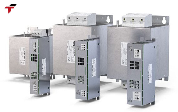
For the mains side, an EMI filter – a combined inductor-capacitor network – attenuates high-frequency conducted EMI propagating toward the utility supply. Effective filter installation requires that all VFD power and ground connections pass through the filter without bypass; any wiring bypass eliminates attenuation performance entirely.
Harmonic and EMI Mitigation Solutions
Choosing the Right Mitigation – Decision Framework
The appropriate mitigation strategy depends on the severity of harmonic distortion, the IEEE 519 compliance requirement, and whether the primary concern is power quality or EMI from the cable installation. Measuring THD at the PCC before selecting a solution prevents both under-engineering and over-engineering.
| Scenario | Primary Symptom | Recommended Solution |
| THD < 8%, single VFD | Minor flicker, no tripping | 3–5% line reactor or DC bus choke |
| THD 8–35%, multiple VFDs on shared bus | Transformer heating, nuisance trips | Passive harmonic filter or 12-pulse topology |
| THD > 35% or IEEE 519 compliance required at drive terminals | Utility penalty risk, critical process | Active harmonic filter |
| Radiated EMI affecting PLC, encoders, or sensors | Signal errors, encoder faults, erratic I/O | Shielded motor cable + dV/dt reactor + EMC zone separation |
| Conducted EMI affecting other loads on same supply | Power supply noise, unexplained load faults | EMI mains filter + common mode choke at VFD output |
Mitigation planned at drive selection stage costs less than retrofitting. Drives with built-in DC bus chokes eliminate one external panel component. Drives with adjustable carrier frequency allow the maintenance engineer to reduce switching frequency in EMI-sensitive periods – trading minor acoustic change for reduced dV/dt and conducted EMI.
Choosing the Right Mitigation – Decision Framework
VFD Selection Considerations for Low-Harmonic Applications
Addressing VFD harmonics at the specification stage costs less than retrofitting harmonic mitigation components after installation. Four specifications are worth confirming during VFD selection where harmonics or EMI are anticipated:
- Built-in DC bus choke or reactor option – eliminates the need for an external line reactor in panel design; confirm whether the choke is standard or a factory option on the selected model
- Adjustable carrier (switching) frequency – allows reduction of switching frequency in EMI-sensitive environments, lowering dV/dt and conducted EMI without changing the drive platform
- CE/EMC compliance marking and emission category – confirms the drive has been tested for conducted emissions; relevant for facilities where VFDs share a distribution board with instrumentation
- Cable entry gland plate with 360° shield termination – structural provision for proper shielded cable grounding; absent on some lower-cost drive enclosures
Flextech supplies inverters from Mitsubishi, Siemens, Panasonic, Toshiba, Xinje, and NAIS – covering cost-optimised SME applications through heavy-duty process drives for semiconductor and palm oil facilities. No single brand suits every application; the right selection depends on load type, communication protocol requirements (Mitsubishi MELSEC network versus Siemens PROFINET), and the harmonic mitigation level built into the drive platform. Contact Flextech and request a quotation with motor load details and distribution system specifications for a matched recommendation.
————————————————————
Summary
VFD harmonics are generated by the 6-pulse rectifier’s non-linear current draw, producing the 5th, 7th, 11th, and 13th harmonic orders that propagate into the distribution network and damage motors, transformers, and capacitor banks. IEEE 519-2014 sets THD below 5% at the PCC for industrial systems – a limit that cumulative multi-drive loading can exceed without active management. Beyond harmonics, VFDs generate conducted and radiated EMI through IGBT switching that requires separate cable and filter-based mitigation. Passive line reactors address moderate THD; multi-pulse topology and active harmonic filters address severe distortion and compliance requirements. The most cost-effective approach addresses harmonic and EMI risk at the drive selection and panel design stage, before installation is complete.
FAQ
What harmonics does a standard 6-pulse VFD produce?
A 6-pulse VFD produces dominant harmonic orders at the 5th (250 Hz), 7th (350 Hz), 11th (550 Hz), and 13th (650 Hz) multiples of the 50 Hz fundamental. These are the characteristic harmonic signature of the 6-pulse diode bridge rectifier topology used in the majority of industrial drives.
What is the IEEE 519-2014 limit for VFD harmonics?
IEEE 519-2014 requires Total Harmonic Distortion (THD) below 5% and individual harmonic distortion below 3% at the Point of Common Coupling (PCC) for systems in the 1 kV to 69 kV range. The PCC for an industrial facility with a dedicated transformer is typically the high-voltage side of that transformer.
What is the difference between a line reactor and an active harmonic filter?
A line reactor adds passive impedance at the VFD input to reduce peak current draw and smooth the harmonic pulse – effective for moderate THD reduction at low cost. An active harmonic filter monitors mainline current in real time and injects an opposing harmonic current to cancel distortion – suitable where IEEE 519 compliance is required at the drive terminals, regardless of load variation.
Can a harmonic filter also reduce EMI from a VFD?
A harmonic filter reduces low-frequency harmonic distortion (5th, 7th, 11th, 13th orders) on the power distribution network. It does not address conducted or radiated EMI generated by IGBT switching at carrier frequencies (2–16 kHz). Conducted and radiated EMI require separate measures: EMI mains filters, common mode chokes, shielded motor cables, and dV/dt reactors.
How do I know if my facility has a VFD harmonic problem?
Four indicators warrant harmonic measurement at the PCC: transformer operating hotter than rated without an overload condition; circuit breakers or fuses tripping without apparent cause; neutral conductor heating in the distribution board; or three or more VFDs drawing from a shared transformer. THD measurement at the PCC with a power quality analyser confirms whether levels exceed the IEEE 519-2014 threshold.
What is the difference between conducted EMI and radiated EMI from a VFD?
Conducted EMI travels through power supply conductors – high-frequency noise from IGBT switching propagates back along the AC supply wires to other loads sharing the same circuit. Radiated EMI propagates through air as electromagnetic fields from the VFD enclosure and motor cable run – primarily driven by high dV/dt at the IGBT output. Each pathway requires different mitigation: conducted EMI needs mains filters and common mode chokes; radiated EMI needs shielded cables and physical separation.