
Proximity Sensor Guide: Types, Sensing Distance and Working Principle

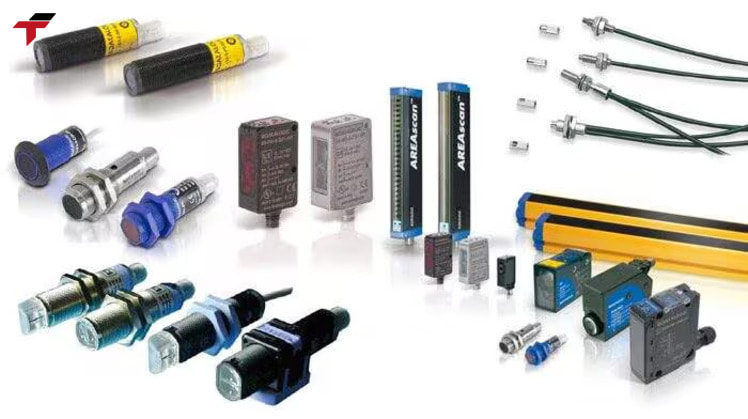
A proximity sensor is a device that detects the presence of a nearby object without any physical contact between the sensor and the target. Malaysian manufacturing lines in semiconductor assembly, palm oil processing, food and beverage, and rubber and glove production rely on proximity sensors to confirm metal part position, count objects on a conveyor, and trigger machine guard interlocks. Five sensing technologies cover almost every industrial use case: inductive, capacitive, magnetic, optical (including infrared), and ultrasonic. Autonics and Omron remain two of the most widely specified proximity sensor brands in Malaysian system integration work, and both are stocked by Flextech Industrial for local sourcing.
This guide covers what a proximity sensor means, its working principle, the five main types and how their sensing distances compare, the proximity switch sensor wiring convention, the schematic symbol, how to test one, and where each type applies on a Malaysian production line.
Proximity Sensor Meaning
Proximity sensor meaning starts from one property: a proximity sensor is an electronic device that detects an object entering its sensing area and converts that detection into an electrical output signal — without the sensor ever touching the target. This non-contact detection is what separates a proximity sensor from a mechanical limit switch, which requires the target to physically press against a lever or plunger to trigger. Because a proximity sensor has no moving parts in contact with the target, it avoids the mechanical wear a limit switch accumulates over repeated cycles, which is why proximity sensors have become the default choice for high-cycle industrial automation.
The term covers a family of detection technologies rather than one specific mechanism. What a proximity sensor means in practice depends on which physical principle it uses to sense the target: an electromagnetic field for metal detection, a capacitance change for mixed materials, a magnetic field for magnet-equipped targets, a light beam for optical detection, or a sound wave echo for longer-range or transparent-target detection. All five share the same basic contract — object enters the sensing area, sensor output switches — but the target material, sensing distance, and installation environment determine which underlying technology fits a given application.
Proximity Sensor Function — How It Works
The proximity sensor function follows the same basic sequence regardless of technology: the sensor generates a field or signal, an object entering the sensing area causes a measurable change in that field or signal, and the sensor’s internal circuitry converts that change into a switched electrical output. What differs between types is the physical mechanism behind the change.
An inductive proximity sensor generates an electromagnetic field at its sensing face. When a metallic target enters this field, eddy currents are induced in the target, which changes the sensor’s electromagnetic response and triggers detection. A capacitive proximity sensor instead monitors the capacitance around its sensing electrode; a target — metallic or non-metallic — entering the electric field changes that capacitance, and the sensor switches its output once the change crosses a threshold. A magnetic proximity sensor detects a change in magnetic field, typically produced by a magnet mounted on the moving target. An optical proximity sensor emits light and reads either the light’s reflection off the target or the interruption of a beam between an emitter and a receiver. An ultrasonic proximity sensor emits a sound pulse and measures the returning echo, with the time delay between transmission and reception indicating that a target is present.
In every case, the sensor’s output stage then converts that internal detection event into a signal a PLC, relay, or controller can read — typically a switched DC voltage on a 2-wire or 3-wire output, described further in the proximity switch sensor section below.
Proximity Sensor Types
The five commonly specified proximity sensor types are inductive, capacitive, magnetic, optical (including infrared), and ultrasonic. Each type suits a different combination of target material, sensing distance, and installation environment, and selecting the wrong type for the target material is a more costly specification error than selecting the wrong brand within the correct type.
Inductive Proximity Sensor
An inductive proximity sensor detects metallic objects only, using the electromagnetic field and eddy-current mechanism described above. Ferrous metals such as iron and steel generally produce the strongest detection response; non-ferrous metals such as aluminium, brass, and copper can have a shorter effective sensing distance depending on the specific sensor model. Inductive sensors are the standard choice in industrial automation for detecting metal components, counting metal parts on a conveyor, and confirming the end position of mechanical parts, precisely because they detect through oil film, dust, and non-metallic contamination without a false trigger.
Capacitive Proximity Sensor
A capacitive proximity sensor detects a change in capacitance at its sensing electrode, which allows it to detect both metallic and non-metallic targets — plastic, powder, granules, and liquids, in addition to metal. This makes the capacitive type the standard choice for liquid-level detection, plastic pellet or granular material sensing, and material presence detection through a non-metallic container wall. The trade-off is environmental sensitivity: humidity and changes in ambient conditions can affect a capacitive sensor’s reading, so sensitivity adjustment matters more for this type than for inductive sensors.
Magnetic Proximity Sensor and Magnetic Proximity Switch
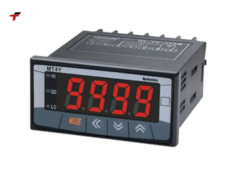
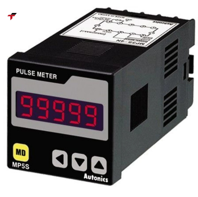
A magnetic proximity sensor — also specified as a magnetic proximity switch — detects the presence of a magnetic field rather than a metal object directly. The typical installation pairs a magnet mounted on the moving part with a magnetic sensor fixed at the detection point; as the magnet approaches, the sensor’s output switches. This arrangement suits position and limit detection on equipment such as pneumatic cylinders, doors, and gates, where a magnet can conveniently be built into the moving component and a long sensing distance is not required. A magnetic proximity switch is a common specification on pneumatic cylinder position sensing in Malaysian packaging and material-handling lines, where the cylinder body already carries a built-in magnetic piston.
Magnetic Proximity Sensor and Magnetic Proximity Switch
Optical and Infrared Proximity Sensor
An optical proximity sensor uses light — most commonly infrared, though visible red and laser variants also exist — to detect an object, either through reflected light or beam interruption between a separate emitter and receiver. Because optical detection does not depend on the target being electrically conductive or magnetic, it can detect materials none of the other four types can reliably sense, including paper, wood, glass, and coloured plastics.
An infrared proximity sensor — often specified simply as a proximity IR sensor — is the most common optical variant in industrial and embedded applications, emitting an infrared beam from an emitter and reading the reflection or interruption at a receiver. Detection performance for this type depends on the target’s colour, reflectivity, transparency, and surface finish rather than on electrical or magnetic properties, and dust or contamination on the optical components can reduce detection reliability over time — a maintenance consideration that inductive and magnetic sensors, with no exposed optics, do not share. The photoelectric sensor is the dedicated optical proximity sensor sub-category built specifically around through-beam, retroreflective, and diffuse light-detection arrangements, and is covered separately in more depth — including symbol, wiring, and Omron/Autonics brand selection.
Ultrasonic Proximity Sensor
An ultrasonic proximity sensor emits a high-frequency sound pulse and measures the returning echo to detect an object, which allows it to sense targets regardless of colour or transparency — a limitation optical sensors do not overcome as reliably. The trade-off is that detection accuracy depends on the target’s shape, surface angle, and the surrounding environment, since a sharply angled surface can deflect the echo away from the receiver. Ultrasonic proximity sensors are the standard choice for longer-range detection, distance measurement, and liquid- or solid-level monitoring in tanks, where inductive and magnetic sensing cannot reach.
Summary So Far
A proximity sensor detects an object without physical contact by generating a field or signal — electromagnetic, capacitive, magnetic, optical, or ultrasonic — and converting the change that object causes into a switched electrical output. The five types divide by target material and sensing mechanism: inductive for metal only, capacitive for metal and non-metal, magnetic for magnet-equipped targets, optical/infrared for most materials via light, and ultrasonic for longer-range or colour-independent detection via sound. How that switched output is wired into a control panel, and what the sensor looks like on a schematic, are the next practical details covered below.
Proximity Switch Sensor — Output Types and Wiring
A proximity switch sensor is the same device described above, specified for its role in a control circuit: switching an output signal on or off as an object enters or leaves the sensing area, rather than producing a continuous analogue reading. “Proximity switch” describes this control-circuit function, not a separate hardware category — most industrial proximity sensors used for object detection operate as switches in this sense.
Two output logic configurations are available on most models: normally open (NO), where the output switches on when a target is detected, and normally closed (NC), where the output switches off when a target is detected. Wiring follows one of two common conventions: a 2-wire configuration, where the sensor’s output is wired in series with the load and power supply, or a 3-wire configuration, with separate power, ground, and output/signal wires — the 3-wire arrangement is the more common specification in PLC-based control panels, since it lets the sensor’s output interface directly with a PLC digital input card without loading the sensor itself. Within 3-wire sensors, NPN and PNP output types determine whether the output switches to ground or to the positive supply rail respectively; confirming which output type a given PLC input card expects, before ordering the sensor, avoids a wiring-stage mismatch that a datasheet check resolves in minutes but a field troubleshooting session can take considerably longer.
Proximity Sensor Symbol
A proximity sensor symbol on an electrical or PLC wiring schematic typically represents the sensor as a rectangular or circular body with a dashed or wavy line indicating the sensing field, positioned facing the target it detects. Where the schematic distinguishes output type, an NPN or PNP transistor symbol appears alongside the sensor body to show how the output connects to the load or PLC input, and a normally open or normally closed contact symbol — the same convention used for mechanical limit switches — indicates the switching logic. This proximity sensor symbol convention differs from a photoelectric sensor symbol, which shows light-beam arrows rather than a field line, since the two device families detect through different physical mechanisms even though both function as non-contact switches on a control drawing.
Confirming the specific symbol and wiring convention against the sensor’s own datasheet remains necessary before installation, since amplifier configuration — self-contained versus separate amplifier — and shielded versus non-shielded mounting can each change how a given inductive or capacitive sensor is represented and wired on the panel drawing.
Proximity Switch Sensor — Output Types and Wiring
Proximity Sensor Sensing Distance by Type
Sensing distance is the primary specification variable once target material and type are chosen, and it varies substantially across the five proximity sensor types.
| Type | Typical Sensing Distance | Target Material |
| Inductive | 1–50mm, up to 50mm (2in / 5.1cm) at the long end | Metal only (ferrous strongest) |
| Capacitive | 3–20mm, up to 20mm (0.8in / 2cm) at the long end | Metal and non-metal (plastic, powder, liquid) |
| Magnetic | Up to ~80mm (3.1in / 8cm), depending on sensor and magnet | Magnetic target or magnet-equipped object |
| Optical / Infrared | 10mm to 100m+, up to 100m (328ft / 3937in) in through-beam configuration | Most materials, light-dependent |
| Ultrasonic | 20mm to 6m, up to 6m (19.7ft / 600cm) at the long end | Most solid and liquid materials |
These ranges are indicative rather than universal: actual sensing distance depends on the specific sensor model, target size, orientation, and mounting — shielded (flush-mountable) inductive sensors, for example, sense at a shorter distance than an equivalent non-shielded model, because the shielding that allows flush metal mounting also reduces field strength. Matching sensing distance to the physical installation gap, rather than defaulting to the longest-range sensor available, keeps detection reliable without paying for range the application does not use.
Proximity Sensor Applications
Proximity sensor applications span industrial automation, robotics, object counting, position and level detection, and safety systems — confirming an object’s presence, position, or count without touching it is the common requirement across all of them.
Industrial automation and conveyor systems depend on proximity sensors to detect metal or non-metal components at fixed points, count parts moving down a line, and confirm that a machine element has reached its intended position before the next operation in the cycle begins. Robotics systems use proximity sensors for obstacle detection and safe operation around moving equipment, often combining inductive or optical types depending on the target materials the robot needs to distinguish. Position and end-of-travel sensing on pneumatic cylinders, gates, and doors typically relies on magnetic proximity switches, while liquid-level and material-level monitoring in tanks and hoppers relies on capacitive or ultrasonic types, chosen according to whether the material is a liquid, powder, or solid. Safety systems apply the same non-contact detection logic to monitor machine guard positions and access points, where a proximity sensor’s absence of mechanical wear supports long-term reliability in a role that a mechanical switch would need to service more frequently.
Proximity Sensor Test Procedure
A proximity sensor test confirms that the sensor detects its target reliably and switches its output correctly before it goes into service or after a suspected fault. The basic test sequence starts with confirming supply voltage at the sensor’s power terminals against the datasheet-specified range, since an out-of-range supply is a common cause of a sensor that appears faulty but is simply underpowered. With power confirmed, the next step brings the intended target material into and out of the sensing area at the specified distance and checks the sensor’s output — most models include an LED indicator that lights when the target is detected, which confirms internal switching before the output is checked at the PLC or control panel end.
If the output does not switch as expected, checking the NO/NC configuration and NPN/PNP output type against what the control circuit expects resolves a common false-fault diagnosis, since a correctly functioning sensor wired with the wrong output logic will appear to fail in exactly the way a genuinely faulty sensor would. For inductive and capacitive sensors, confirming that the target material and size match what the sensor is rated to detect is the next check, since a target that is too small, too far, or the wrong material for the sensor type can produce an intermittent or absent detection that is not a hardware fault at all.
Proximity Sensor Test Procedure
Choosing a Proximity Sensor for Malaysian Production Lines
Selecting a proximity sensor starts with target material — the single factor that eliminates most of the five types from consideration before sensing distance or environment is even evaluated. A metal-only target points toward inductive; a mixed-material or liquid target points toward capacitive or ultrasonic; a magnet-equipped moving part points toward magnetic; and a target requiring detection regardless of material composition points toward optical or infrared.
Autonics and Omron are two of the proximity sensor brands most frequently specified by Malaysian system integrators, and both are carried in Flextech Industrial’s automation sensors Malaysia range for local sourcing. An Omron proximity sensor is a common specification choice in semiconductor and precision manufacturing lines, sectors where Omron’s broader automation product line — PLCs, HMIs, and sensors — already forms part of the installed control system, simplifying integration and spare-parts sourcing under a single brand. An Autonics proximity sensor is a frequent specification choice where cost-competitive procurement matters alongside reliable detection performance, a combination that suits packaging, F&B, and general manufacturing lines common across Malaysian SME production facilities. As with PLC and inverter brand selection across Flextech’s product range, the right proximity sensor brand and type depend on the application’s target material, sensing distance, and installed control system — not on a single brand being categorically superior — and sourcing locally avoids the import lead time that can otherwise stall a line commissioning schedule.
Frequently Asked Questions
Type, symbol, and testing questions are covered above; these questions address distinctions that come up most often once a proximity sensor is already being specified or wired into a panel.
What is the difference between an inductive and a capacitive proximity sensor?
An inductive proximity sensor detects only metallic targets, using eddy currents induced by an electromagnetic field, and generally provides the strongest detection on ferrous metals. A capacitive proximity sensor detects both metallic and non-metallic targets — including plastics, powders, and liquids — by sensing a change in capacitance, which makes it the correct choice whenever the target is not metal.
Can a proximity sensor detect non-metal objects?
It depends on the type. Inductive proximity sensors detect metal only. Capacitive, optical/infrared, and ultrasonic proximity sensors can all detect non-metal objects — capacitive sensors are commonly specified for plastics, powders, and liquids, while optical and ultrasonic sensors detect most materials regardless of electrical conductivity.
What is another name for a proximity sensor?
A proximity sensor used for on/off object detection is also referred to as a proximity switch, and the device functions in the same role a mechanical limit switch performs, without physical contact. Type-specific names — inductive sensor, capacitive sensor, photoelectric sensor — also describe the same general device family, distinguished by sensing mechanism.
How far can a proximity sensor detect an object?
Sensing distance depends entirely on the type: inductive sensors typically reach 1–50mm, capacitive sensors 3–20mm, magnetic sensors up to roughly 80mm depending on the magnet, optical/infrared sensors from 10mm up to 100 metres or more in a through-beam configuration, and ultrasonic sensors from 20mm up to around 6 metres. Choosing a type based on the required distance, not just the target material, narrows the specification faster.