In industrial automation systems, HMI and Modbus are two important components, helping to connect and monitor devices easily and save costs. However, not everyone understands how to configure, program and exploit Modbus effectively on HMI. The following article will guide you on how to use Modbus in HMI from operating principles, configuration steps to security notes, helping your system operate stably and expand more easily.
What is Modbus?
Modbus is an industrial communication protocol developed by Modicon (now Schneider Electric) in 1979, designed for data exchange between controllers, sensors, and monitoring devices. It has since become one of the most widely used open protocols in industrial automation thanks to its simplicity, flexibility, and compatibility across vendors.
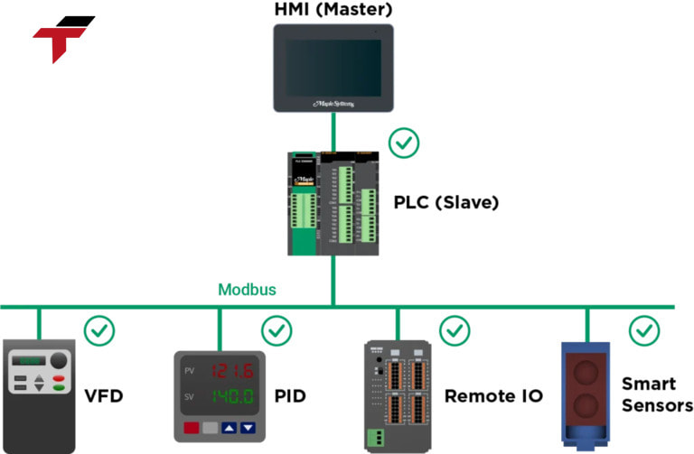
In a modern factory, Modbus acts as a common communication language between devices such as PLCs, HMIs, inverters, and sensors. Through Modbus, operational data like measurements, control signals, and system status are transmitted accurately and in real time — enabling centralized monitoring, better process control, and cost efficiency.
Modbus is an industrial communication protocol developed by Modicon (now Schneider Electric) in 1979
How to Use Modbus in HMI?
To set up Modbus communication in an HMI system effectively, technicians should follow a structured workflow that ensures stable data exchange, accurate monitoring, and safe operation.
Hardware Connection
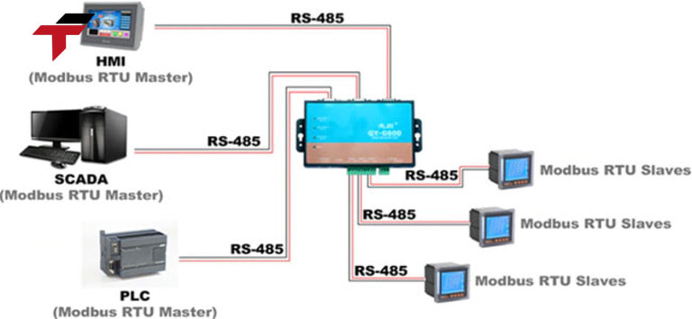
The first step is to establish a physical connection between the HMI and the target device — such as a PLC, inverter, or sensor. For Modbus RTU: Use RS-232 (short distance) or RS-485 (multi-drop, longer distance) communication ports.
- RS-232 connects directly between one HMI and one device.
- RS-485 supports up to 32 devices on the same communication line.
For Modbus TCP: Connect the HMI and devices through an Ethernet network (TCP/IP), either via a direct LAN cable or an industrial switch.
Important notes:
- Use industrial-grade shielded twisted-pair cables to minimize electromagnetic interference (EMI).
- Keep communication cables separated from high-voltage or power lines.
- Ground the cable shield properly at one end only to prevent signal loops.
- Ensure terminal resistors (typically 120Ω) are installed at both ends of an RS-485 line for stability.
Configure Communication Parameters
Once the hardware connection is complete, configure the communication parameters in both the HMI (Master) and connected device (Slave).
The key parameters include:
- Slave Address (Node ID): A unique number identifying each device on the Modbus network.
- Baud Rate: Defines the speed of data transmission (commonly 9600 or 19200 bps).
- Data Bits, Parity, Stop Bits: Must be identical between all devices to ensure synchronization.
- Communication Mode: Select between Modbus RTU or Modbus TCP, depending on the setup.
Tips from Flextech engineers:
- Always cross-check device manuals for supported baud rates and parity options.
- When using multiple slaves, document each address clearly to avoid duplication.
- Test one device at a time before connecting the entire network — this helps isolate configuration errors early.
Data Mapping
Data mapping defines how information from the Slave device (PLC, sensor, etc.) is read and displayed on the HMI. Each data type in Modbus corresponds to a register group:
| Register Type | Address Range | Data Type | Typical Use |
| Coils | 0xxxx | 1-bit | Output control (ON/OFF) |
| Discrete Inputs | 1xxxx | 1-bit | Digital input status |
| Input Registers | 3xxxx | 16-bit | Read-only analog inputs |
| Holding Registers | 4xxxx | 16-bit | Read/Write analog values |
In the HMI software, create corresponding data tags for each register that you want to monitor or control.
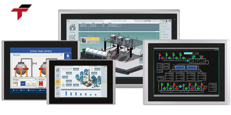
Design the HMI Interface
After mapping data, link tags to visual elements on the HMI screen to create an intuitive and user-friendly interface.
- For monitoring: Use gauges, bar graphs, numeric displays, or trend charts to show live process values.
- For control: Add push buttons, switches, or setpoint inputs linked to Modbus coils or holding registers.
- For diagnostics: Include status indicators (green/red lights) to show communication or alarm conditions.
Test and Run
Before putting the HMI into full operation, conduct a complete system test to validate all connections and data exchanges.
- Check that all real-time data on the HMI match the actual device values.
- Confirm that command buttons correctly control outputs (start/stop, setpoints, etc.).
- Observe for delays or missing updates — signs of communication instability.
- If using Modbus RTU, verify termination and shielding; for Modbus TCP, confirm IP address settings and ping results.
Once the system operates stably:
- Save and back up the HMI project file, Modbus mapping, and communication parameters.
- Document the configuration for future reference or expansion.
- Schedule periodic revalidation to ensure consistent performance.
To set up Modbus communication in an HMI system effectively, technicians should follow a structured workflow
Why is Modbus often integrated in HMI?
In order for HMI to communicate effectively with devices such as PLCs, inverters, sensors, it is mandatory to use a popular, easy-to-deploy communication protocol – and Modbus is the most popular choice.
- Popularity and high standardization: Modbus is one of the oldest industrial communication protocols, supported by thousands of equipment manufacturers around the world.
- Easy to configure, quick to deploy: Compared to other complex protocols, Modbus has a simple data frame structure, clear configuration process. Users only need to determine the correct device address, communication parameters (baud rate, parity …) and register mapping to be able to transmit and receive data immediately.
- Diverse connection standards: Modbus supports both serial transmission (Modbus RTU – RS-232/RS-485) and transmission via Ethernet (Modbus TCP). This helps to flexibly design the system, from small scale (point-to-point serial) to large scale (LAN).
- Optimizing investment costs: Thanks to Modbus, businesses do not need to invest in additional expensive gateway modules to connect devices from other manufacturers. All data is transmitted via a common protocol, HMI only plays the role of collecting, displaying and controlling.
- Easy expansion: When needing to add new devices, users only need to install additional Slave addresses and register mapping, without having to change the entire system. This helps businesses save time and costs to expand the line.
With the above advantages, Modbus is almost the default choice when building HMI systems in automation – from production lines, water treatment stations, power plants to industrial IoT solutions.
In order for HMI to communicate effectively with devices such as PLCs, inverters, sensors
What are the common errors when using Modbus in HMI?
During the process of setting up and operating Modbus with HMI, users often encounter some of the following common errors:
Slave device not recognized
- This error often occurs when the physical connection (cable, COM port) is incorrect, or the Slave device is not fully powered.
- How to handle: Check the cable, communication port, make sure the Slave is operating and in the correct communication mode.
Incorrect address or communication parameters:
- Modbus requires the Slave address, baud rate, parity bit to match between the Master (HMI) and Slave. Small deviations can also cause communication failure.
- How to handle: Verify the Slave address again, check parameters such as baud rate, stop bit, parity according to the device’s instructions.
Transmission signal interference error:
- When using Modbus RTU via RS-485, long signal wires running parallel to the power cord can cause interference.
- How to handle: Use anti-interference cable, add signal repeater if the distance is long, or install standard transmission line termination resistors.
Quick fix
- Use Modbus test software to check each device separately.
- Read the error log of HMI or PLC to isolate the problem.
- Update device firmware if necessary.
4 common errors when using Modbus in HMI
What to note when deploying Modbus in HMI?
To ensure the HMI system communicates via Modbus stably, durably and safely, you need to pay attention to the following important points:
- Transmission security: Use firewalls and VLAN segregation to isolate the automation network from office systems, and assign clear user permissions to prevent unauthorized access. Always set passwords, keep firmware updated, and use VPN or encrypted connections when remote access is required.
- Choose the right cable and connection standard: If using Modbus RTU, prioritize quality RS-485 cables with anti-interference layer. The line should be separated from the power cord to limit signal interference, keeping the connection stable.
- Backup and check regularly: Regularly back up HMI configuration files, Modbus parameters, and tag mapping after each adjustment. Schedule periodic inspections (every 3–6 months) to check for loose cables, verify communication parameters, and review error logs for early signs of signal loss or timeout.

To ensure the HMI system communicates via Modbus stably, you need to pay attention to the following important points
Conclusion
Integrating Modbus in HMI offers significant advantages for industrial automation — from seamless multi-device connectivity and simple configuration to optimized performance and long-term cost efficiency. When engineers fully understand Modbus principles, setup procedures, and key factors such as network security, connection standards, and preventive maintenance, the system can operate with maximum stability and precision.
At Flextech Industrial, we specialize in HMI and Modbus integration solutions tailored for each production environment — ensuring fast, reliable data communication and easy system expansion. Our technical team provides full support from configuration to commissioning, helping businesses build a connected, efficient, and future-ready automation system.
If you’re seeking to enhance your HMI–Modbus performance or need expert guidance in automation communication, contact Flextech Industrial for dedicated consultation and implementation support.

