A servo system diagram illustrates the interconnection between PLCs, servo drivers, motors, and feedback devices in a motion control system. For engineers, correctly understanding and applying the diagram ensures quick installation, stable operation, and simplified troubleshooting. This article by Flextech explains the concept, structure, and practical considerations of servo system diagrams in industrial automation.
What is a servo system diagram?
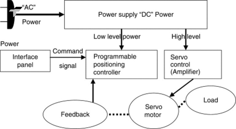
In automation, a servo system diagram visually represents how the key components of a servo control system interact with each other. It shows the path of electrical power and control signals between the controller (PLC), servo driver, servo motor, and feedback devices.
Depending on the technical requirement, servo system diagrams are often displayed in several forms:
- Block Diagram: Highlights control and feedback flow between core components – useful for basic understanding or presentations.
- Wiring Diagram: Details power lines, signal lines, and pin connections between PLCs, drivers, motors, encoders, and sensors – essential for installation.
- Signal Flow Diagram: Focuses on control and feedback direction to help engineers during programming or troubleshooting.
What are the main components in a servo system diagram?
A servo system diagram is not simply a drawing of connections between devices, but also clearly shows the roles and relationships between the core components of a precision motion control system. Below are the components that often appear in a standard servo system diagram:
- Controller (PLC / HMI): Acts as the system’s “brain,” sending motion commands such as position, speed, or torque to the driver. When integrated with an HMI, it also allows operators to monitor and adjust system parameters easily.
- Servo Driver (Amplifier): Receives control signals from the PLC and converts them into electrical energy suitable for the motor. It also performs internal control loops (position, speed, torque) to maintain smooth and accurate motion.
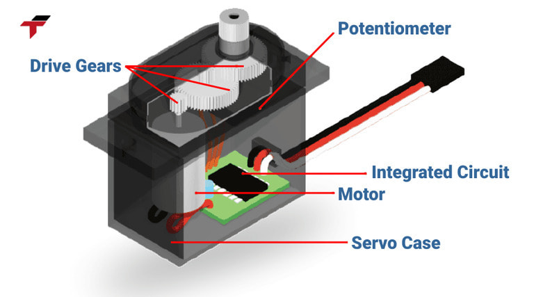
- Servo Motor: Converts electrical energy into mechanical movement. It delivers precise rotation, position, or torque control, ensuring fast response and stability—ideal for robotics, conveyors, or CNC machinery.
- Feedback Device (Encoder / Resolver): Continuously measures the motor’s position and speed, sending real-time feedback to the driver. This closed-loop control helps maintain high accuracy and stable performance under varying loads.
Servo Driver (Amplifier):
What are the benefits of the Diagram Servo System for businesses?
Using the servo system diagram – servo system diagram – not only helps to clearly visualize the system structure but also brings many practical benefits in the design, construction and operation process.
- Support for accurate system design and implementation from the beginning: Diagram helps engineers easily determine the number of devices needed, how to connect between PLC – driver – motor – encoder – sensor. Minimize errors in the installation stage, avoid confusing signal pins or power sources.
- Save time: Clear diagrams help technicians quickly identify the location of each connection port, I/O signal, power supply. No need to waste time looking up individual device manuals.
- Easy maintenance and troubleshooting: When the system has an error (for example, the motor does not rotate, loses feedback from the encoder, etc.), the diagram helps to quickly localize the location that needs to be checked. Limit unnecessary disassembly or widespread inspection.
- Optimize servo system performance: Correctly understanding the system diagram helps engineers configure the optimal driver/motor for each specific application. Increase accuracy, stability of movement, reduce power consumption.
Benefits of the Diagram Servo System for businesses
What are the things to consider when choosing a Servo System Diagram?
Choosing a suitable servo system diagram not only helps the system operate properly but also avoids errors that cause equipment damage or incorrect operation. Below are the factors that need special attention when choosing a servo system diagram for practical applications:
- Suitable for the type of equipment being used: Driver and motor must be of the same brand or compatible with the connection standard. What type of PLC is the controller? Does it support communication protocols such as Modbus, EtherCAT, CANopen?
- Check the number of axes and required control functions: Use a 1-axis, 2-axis or synchronous multi-axis servo? Do you need to control position, velocity or torque?
- Make sure to clearly show the control and feedback signal flow: Signal direction: from PLC → driver → motor → encoder feedback to driver. The location of the sensor and limit switch in the diagram must also be clearly illustrated.
- Correct with the voltage and power standard at the factory: Does the servo use a single-phase or three-phase power source? Is the voltage 220VAC or 380VAC? If the diagram is not correct with the voltage standard, it can cause short circuits in the equipment or driver power errors.

Choosing a suitable servo system diagram not only helps the system operate properly but also avoids errors that cause equipment damage
In which fields is the Servo System Diagram commonly applied?
The Servo System Diagram is more than just a technical drawing — it is an essential tool that supports system design, operation, and maintenance across a wide range of industrial environments. By mastering how to read and use this diagram, engineers and technicians can ensure smoother workflows, faster troubleshooting, and higher productivity. Common areas of application include:
- Installation of motion control systems: During system setup, electrical and automation engineers rely on the servo system diagram to correctly connect PLCs, servo drivers, motors, sensors, and encoders.
- Maintenance and troubleshooting of servo systems: When issues arise—such as encoder feedback loss, servo alarm, abnormal vibration, or limit switch activation—the servo diagram becomes a “troubleshooting map.” Maintenance staff can quickly trace the root cause by following the signal flow and checking each connection step-by-step.
- Technical training and skill development: In manufacturing companies or automation service providers, servo system diagrams are key learning materials for new technicians and engineers. Through the diagram, learners can easily visualize how control signals, feedback loops, and power circuits interact in a servo system.
- System design and process optimization: Design engineers use servo system diagrams during the planning phase to select compatible equipment, define signal routing, and verify safety interlocks.
The Servo System Diagram is more than just a technical drawing
Conclusion
A well-understood and properly applied Servo System Diagram is essential to achieving precision, stability, and long-term reliability in any automation setup. It not only helps systems operate efficiently but also reduces installation time, maintenance costs, and potential technical failures throughout the entire production lifecycle.
For engineers and automation specialists, the diagram serves as an indispensable guide — supporting every phase from system design, wiring, and programming to troubleshooting and optimization.
At Flextech, we offer comprehensive servo solutions including motors, drivers, PLCs, and expert consultation on system configuration and wiring diagrams tailored to your real-world applications. If you’re looking to design or upgrade your servo system with reliable, high-performance equipment, our technical team is ready to assist you with professional guidance and practical solutions.

