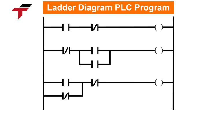
Ladder logic programming is one of the five commonly used languages in PLCs. It is inspired by conventional electrical relay circuits and further developed to optimize complex industrial processes such as assembly lines, conveyors, packaging, machinery, and equipment manufacturing.
Ladder logic is often the preferred programming method due to its intuitive, user-friendly graphical interface and outstanding benefits that significantly improve monitoring and control capabilities, helping to maintain efficiency across an entire automated system.
If you are looking to learn more about this essential programming language, continue reading. This guide will provide valuable insights into ladder logic, its applications, and how to effectively develop ladder logic systems.
Where is Ladder Logic Commonly Used?
While many are aware of the utility of ladder logic programming, its broad application across various industries makes it a vital skill. Some common applications include:
- Motor Control: Ladder logic governs the entire operation of industrial motors, controlling everything from starting, managing, and monitoring the speed and direction of movement to the final stopping sequence.
- Conveyor Systems: Similar to motor control, ladder logic is frequently used to manage large-scale conveyor lines in factories. It supports the deployment and operation of product movement direction, monitors operations, and automatically stops the system if operational risks are detected.
- Assembly Lines: This programming method is extensively used in the automotive, electrical, and electronic equipment manufacturing sectors. It specializes in coordinating robot operations, ‘pick and place’ tasks, and ensuring precise, correct-position assembly for each product.
- Packaging and Palletizing Lines: In the packaging industry, ladder logic coordinates equipment like filling machines, cartoning machines, and palletizing machines. The system meticulously controls each operation, ensuring all products are packaged according to pre-defined parameters.
Where is Ladder Logic Commonly Used?
Why is Ladder Logic So Popular?
Ladder logic programming is a highly favored programming method today, largely due to several key factors:
- User-Friendly Graphical Interface: Its visual nature closely resembles traditional relay circuit simulation diagrams. This makes the transition from conventional circuits to ladder logic simple for both experienced technicians and newcomers.
- Ease of Use: It allows for quick code development within the PLC environment.
- Simplified Troubleshooting: The left-to-right, top-to-bottom logic flow makes observing the program execution straightforward, which greatly simplifies the process of identifying and troubleshooting problems.
What are the Advantages and Disadvantages of Ladder Logic Programs?
The rise of ladder logic programming has brought numerous benefits to automated factories, robots, and various production lines, but it also has limitations.
Advantages
- Easy Debugging: Technicians can visually observe the overall electrical flow and graphical representation of the entire circuit, making the debugging process easier and faster.
- Efficiency and Reliability: Circuits designed with ladder logic programming are often more efficient and reliable than complex setups using discrete electrical components.
- High Flexibility: It offers a variety of graphics with high flexibility and functionality, making it suitable for complex production lines and tasks.
- Easy Monitoring and Maintenance: The structure is well-suited for large-scale production units that require advanced programming structures for effective monitoring, management, and maintenance.
Disadvantages
- Limited Data Structure: Data is typically restricted to single bits or registers, which can complicate the grouping and protection of complex data sets.
- Inflexible Execution Control: Ladder diagrams execute strictly from left to right, top to bottom. This sequential execution can make it challenging to build applications that require multi-speed feedback or precise analog control (like PID loops) that demand consistent and fast execution times.
- Limited Arithmetic Operations: While ladder diagrams support mathematical operations (addition, subtraction, etc.), they are not as flexible as other tools for complex algorithms, as the input/output of function blocks must be referenced indirectly through memory locations.
What Components Does Ladder Logic Include?
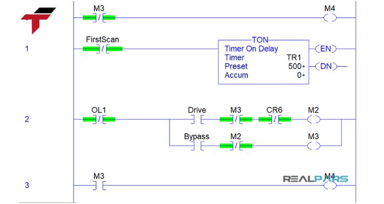
Ladder logic, a foundational PLC programming language, uses graphical elements inspired by electrical relay circuits to monitor and control industrial processes. These essential components form the structure of every program rung, dictating the flow of power and logic.
The main components found in any ladder logic program include:
- Contacts (Inputs): These represent input devices like switches or sensors..
- Coils (Outputs): These represent output devices such as motors, solenoids, or indicator lights, and are activated based on the logic preceding them.
- Timers: Used to introduce time-based actions. Common types are TON (Delay-On), TOF (Delay-Off), and RTO (Retentive).
- Counters: Used to track and control actions based on the number of events, including Increment (count up) and Decrement (count down) functions.
- Math and Comparison Functions: Blocks used for arithmetic operations and comparing data values within the program.
What Components Does Ladder Logic Include?
How to Develop a Complete Ladder Logic Program
Developing a complete PLC ladder logic program requires a structured approach to ensure the final installation meets all desired business and operational requirements. The essential steps are:
Planning and Design
Start by clearly defining all input and output devices, the required operational process, and the specific control logic. Creating a complete flow chart of the process is highly recommended. This visual planning helps to easily visualize the operating mechanism, identify potential errors early, and simplify subsequent edits.
Choose a Programming Language
While you are focusing on Ladder Diagram (LD), modern PLCs often support other languages like Structured Text (ST). The choice of language depends on the complexity of the process, the desired goals, and the programmer’s familiarity. For systems heavily reliant on sequencing and interlocking, LD is often the best choice, aligning with the project’s specific requirements.
Write the Program
This is the stage where you create the ladder logic diagrams, implementing timers, counters, mathematical functions, and developing a modular programming structure. Always adhere to established naming conventions and apply thorough documentation. This ensures the program is written in a way that is easy to understand, debug, and maintain in the future.
Test and Debug
Once the program is written, rigorous testing is mandatory. Use simulation tools or a test bench to easily detect and promptly edit any errors in the logic. Any program errors must be identified and corrected immediately to prevent performance issues once the system is deployed.
Deploy
After all testing and debugging steps are completed and verified, the program can be safely deployed into the industrial system to monitor and control your operations.

