In automation and control systems, selecting the correct signal output type is essential to ensure reliable communication between devices such as sensors, servo drivers, and PLCs. Among these, Sourcing Output (PNP) is one of the most widely used standards today due to its safety, stability, and compatibility with modern industrial equipment.
This article from Flextech will explain what PNP output is, how it works, its advantages over NPN (Sinking Output), and practical recommendations for designing or upgrading automation systems.
What is Sourcing Output (PNP)?
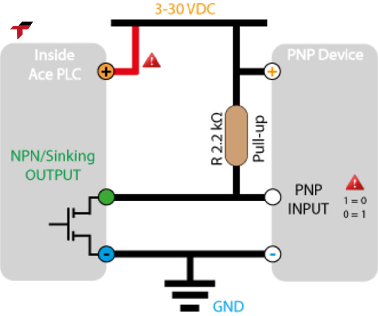
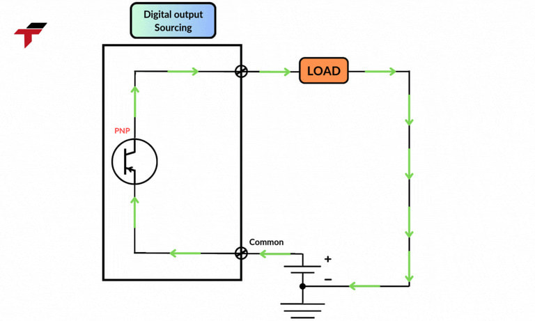
Sourcing Output (PNP) refers to a configuration where the output device supplies positive voltage (+V) to the load when activated (ON). The other side of the load is connected to ground (GND), forming a complete circuit.
In simpler terms, a PNP output “sources” current — meaning it pushes current from the positive terminal of the power supply, through the output device, and into the load before returning to ground.
This setup is extremely common in European industrial standards, automation lines, and servo control systems due to its electrical safety and ease of integration.
What are the advantages of Sourcing Output (PNP)?
PNP outputs provide many operational and safety benefits that make them ideal for complex automation environments:
- Enhanced safety for operators: Since the output provides a positive voltage instead of connecting to ground, accidental contact is less likely to cause short circuits or electrical shocks.
- Reduced electrical noise: The PNP system transmits signals at a higher voltage level (+24V), which makes it more resistant to electromagnetic interference (EMI) – a common issue in factories with motors, inverters, and high-current devices.
- High compatibility with modern PLCs: Most PLC brands such as Siemens, Omron, Mitsubishi, Delta, and XINJE natively support PNP logic inputs, allowing direct connection without additional converters.
- Clear and intuitive logic state indication: A high signal (+V) represents an ON state, while 0V (GND) represents OFF, making diagnostics, LED indicators, and HMI monitoring much easier to interpret.
- Simplified wiring for multi-sensor systems: PNP allows the use of common grounding for multiple sensors, simplifying electrical design and reducing wiring errors.
Sourcing Output (PNP) is one of the most widely used standards today
When to choose PNP for servo systems?
Choosing PNP (sourcing output) or NPN (sinking output) output not only depends on technical preferences, but is also directly related to system compatibility and operational safety. Here are some criteria to help you determine which PNP to choose:
- Use a PLC that supports PNP input: If the main controller (such as a PLC or HMI) requires a high logic level (+24V) to activate the signal, PNP is the right choice.
- Input sensors and relays also use PNP: The system will be more stable if all devices have the same signal type. Avoiding mixing PNP and NPN will help simplify the circuit diagram and limit logic errors.
- Safety and low noise requirements: In industrial environments with a lot of electrical noise or requiring better operator protection, PNP outputs are often preferred.
- In case of upgrading an old system: If the system is using NPN but you want to upgrade to a new device (servo driver, PLC, etc.) that better supports PNP, consider synchronizing the entire signal.
What are the notes when designing or connecting PNP signals?
To ensure that the PNP (sourcing output) signal works stably and safely in industrial servo or PLC systems, engineers need to follow several essential design and wiring principles. These factors not only help maintain reliable communication between devices but also protect components from signal loss or electrical damage.
- Connect the power source and PLC logic in the correct direction: The PNP output provides a positive voltage (+V) to the load, and the return path of the circuit must go through GND (ground). Therefore, the input terminals of PLCs, HMIs, or servo drivers must be properly connected to GND.
- Check the output load and current capacity: Each PNP output port can only handle a certain amount of current (typically between 100–500 mA depending on the device). When connecting to external loads such as relays, solenoid valves, or indicator lamps, ensure that the total current draw does not exceed the rated limit.
- Apply anti-interference and circuit protection measures: Industrial environments are full of electromagnetic interference (EMI) from motors, inverters, and high-power equipment. To protect PNP signals, use components such as flyback diodes across inductive loads, filter capacitors to smooth out signal fluctuations, and optocouplers for electrical isolation.
- Separate signal wires and power lines: When routing cables, keep signal and power lines apart to prevent cross-talk and noise interference. Using shielded cables for PNP signals and grounding one end of the shield can significantly improve noise immunity.
- Perform grounding and common reference checks: Make sure that all devices in the system (PLC, driver, sensors, etc.) share a common ground reference. Floating or inconsistent grounding points can cause unstable voltage levels and false signal triggering.

To ensure sourcing output signal works stably and safely in industrial servo engineers need to follow several essential design and wiring principles.
Common errors when using PNP and how to fix them?
Although PNP signals are considered safe and popular in control systems, if users do not understand the operating principles and connection diagrams, they can still easily encounter the following errors:
Incorrect input voltage supply
- Cause: One of the most common mistakes is supplying the wrong voltage level from the PNP output to the receiving device (such as PLCs, servo drivers, or sensors). This often occurs when multiple power sources or devices from different manufacturers are used in one system.
- Solution: Always verify the rated voltage of both the output and the receiving device — typically 24VDC. Ensure that all components share the same voltage standard to avoid input overload or non-response.
Incorrect signal polarity
- Cause: PNP outputs “source” positive voltage to the load, which must return through GND. Reversing the wiring (for instance, connecting the load to V+ instead of GND) can cause signal failure, short circuits, or even component damage.
- Solution: Double-check the power (+), signal, and GND pins on each device before wiring. Using a multimeter to confirm polarity before powering on is a safe practice.
Unstable signal when the load is small
- Cause: When connecting to high-impedance input devices like microcontrollers or digital input modules, the current through the PNP output may be too small for a stable signal, causing flickering or erratic logic levels.
- Solution: Add a pull-down resistor (10–20kΩ) between the signal line and GND, or use signal buffers or opto-isolators to strengthen and stabilize the output.
Signal noise in industrial environments
- Cause: In manufacturing facilities, electromagnetic interference (EMI) from motors, contactors, or inverters can distort long or unshielded signal lines, leading to unstable or delayed signal transmission.
- Solution: Use flyback diodes across inductive loads, filter capacitors, or opto-isolation circuits to protect against voltage spikes. Additionally, shielded cables and proper grounding practices can further minimize EMI effects.
Incorrect input voltage supply
Conclusion
Sourcing Output (PNP) has become the preferred standard for modern automation systems due to its high safety, stable signal transmission, and seamless compatibility with PLCs and servo drives.
When properly designed and installed, PNP connections ensure accurate communication, improved reliability, and reduced maintenance for factory automation.
At Flextech, we provide expert consulting and integrated solutions for designing and configuring PNP-compatible control systems — helping businesses optimize performance, minimize downtime, and enhance operational safety.

